Photonic Technique For Generating Arbitrary Waveforms

a photonic and waveform technology, applied in optics, instruments, electrical equipment, etc., can solve the problems of insufficient dynamic range of the awg designed with parallel amplitude-switching modulators, and the modulator corresponding to the least significant channel is too weak

Active Publication Date: 2011-06-23
RPX CORP +1
View PDF4 Cites 0 Cited by
  • Summary
  • Abstract
  • Description
  • Claims
  • Application Information

AI Technical Summary

Benefits of technology

[0005]The dynamic range of the AWG designed with parallel amplitude-switching modulators is undesirably limited due to a low extinction ratio of the amplitude modulators therein. This limitation sterns from the fact that in one such AWG, the signal from an amplitude modulator corresponding to the least significant channel would be too weak to be differentiable from the leakage of the stronger signal from another amplitude modulator corresponding to the most significant channel. An embodiment of the invention overcomes such a dynamic range limitation by designing an AWG with a phase-modulation device including, e.g., sequential optical phase modulators, instead. Thus, in accordance with one embodiment of the invention, a phase-modulation device is used to phase-modulate a first optical carrier signal having a given phase, resulting in a phase-modulated optical signal whose phase differs from the given phase by a phase value which is controllable by one or more inputs to the device. A second optical carrier signal having the given phase is combined with the phase-modulated optical signal to provide a waveform whose amplitude varies with the phase value. Thus, by manipulating the inputs as a function of time, one can control the phase value to arbitrarily shape the waveform.

Problems solved by technology

The dynamic range of the AWG designed with parallel amplitude-switching modulators is undesirably limited due to a low extinction ratio of the amplitude modulators therein.
This limitation sterns from the fact that in one such AWG, the signal from an amplitude modulator corresponding to the least significant channel would be too weak to be differentiable from the leakage of the stronger signal from another amplitude modulator corresponding to the most significant channel.

Method used


Image

  • Photonic Technique For Generating Arbitrary Waveforms
  • Photonic Technique For Generating Arbitrary Waveforms
  • Photonic Technique For Generating Arbitrary Waveforms

Examples


Embodiment Construction

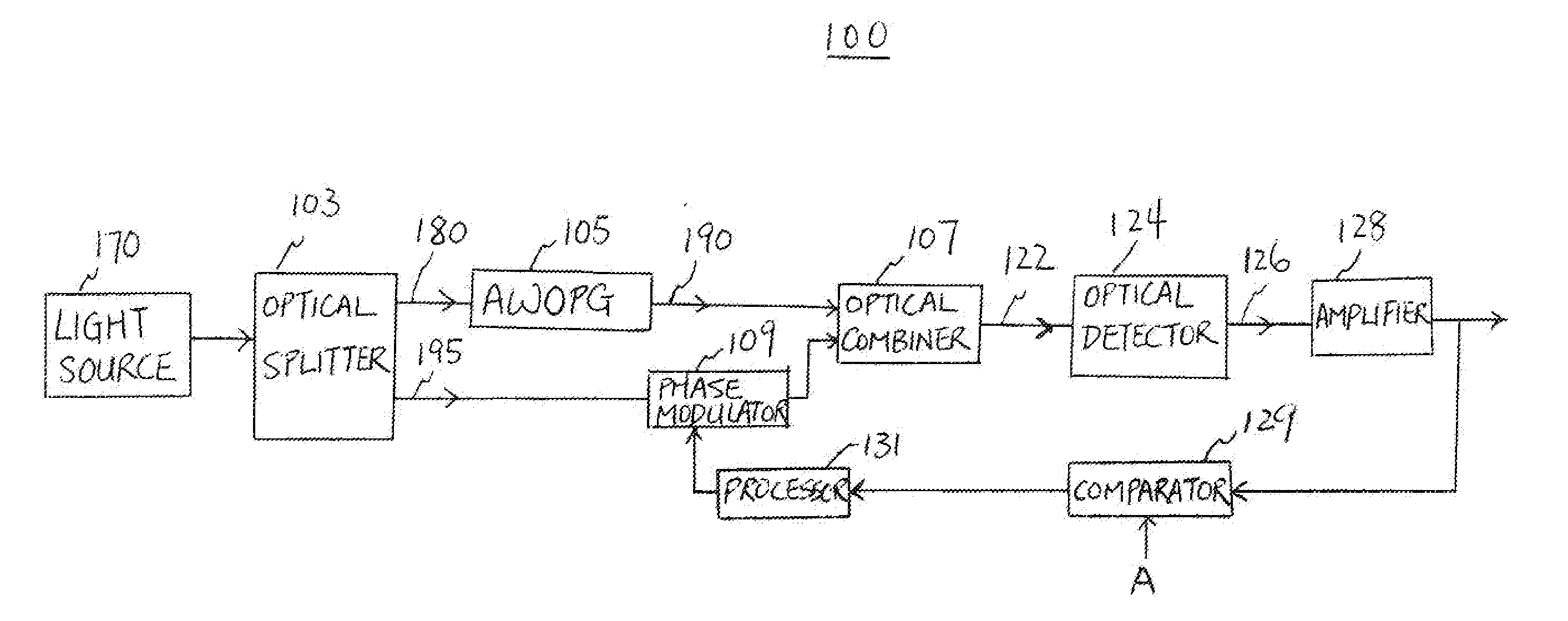
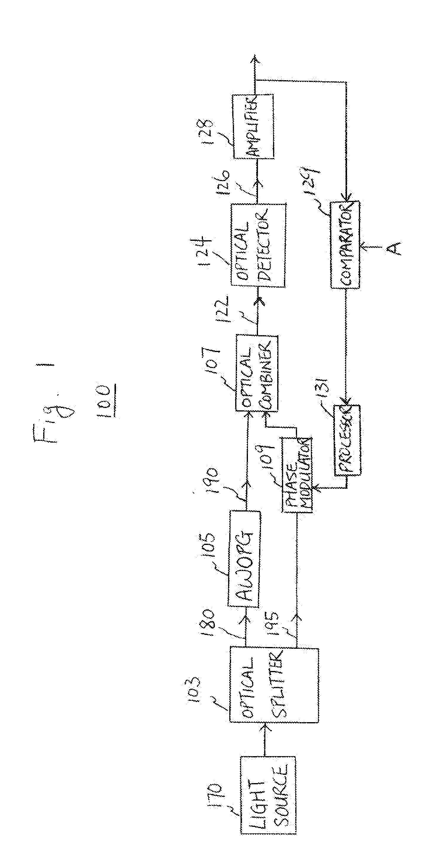
[0012]FIG. 1 illustrates a radio frequency (RF)-photonic arbitrary wave generator (AWG) 100 embodying the principles of the invention. In one embodiment, AWG 100 is realized using arbitrary waveform optical phase generator (AWOPG) 105, which is different from a common AWG designed with parallel amplitude-switching-modulators. The latter has a lesser dynamic range, stemming from the fact that the signal from its amplitude modulator corresponding to the least significant channel would be too weak to be differentiable from the leakage of the stronger signal from its other amplitude modulator corresponding to the most significant channel.

[0013]As illustrated in FIG. 1, light source 170 in AWG 100 may be, e.g., a visible or invisible coherent optical source such as a laser diode. It provides an optical carrier, which is split by optical splitter 103 to form two identical optical carrier signals, denoted 180 and 195, respectively. By way of example, optical carrier signal 180, which is fe...


PUM

PropertyMeasurementUnit
phaseaaaaaaaaaa
electrical waveformaaaaaaaaaa
phase shiftaaaaaaaaaa

Abstract

In a radio frequency (RF)-photonic arbitrary waveform generator (AWG), an optical carrier signal is phase-modulated using an arbitrary waveform optical phase generator (AWPOG), which may include, e.g., sequential optical phase modulators. The phase-modulated optical signal is combined with a version of the optical carrier signal to yield an optical waveform, whose amplitude varies with a phase shift introduced by the AWPOG to the optical carrier signal. By manipulating electrical inputs to the AWPOG which control the phase shift, the optical waveform can be arbitrary shaped. The optical waveform may then be converted to an electrical waveform having a radio frequency.

Description

CROSS-REFERENCE TO RELATED APPLICATIONS[0001]This application is a continuation-in-part of U.S. patent application Ser. No. 12 / 641,601, filed on Dec. 18, 2009, which is incorporated herein by reference in its entirety.FIELD OF THE INVENTION[0002]The invention relates to a signal generation technique and, more particularly, to a technique for generating arbitrary waveforms using photonics.BACKGROUND OF THE INVENTION[0003]This section introduces aspects that may help facilitate a better understanding of the invention. Accordingly, the statements of this section are to be read in this light and are not to be understood as admissions about what is prior art or what is not prior art.[0004]An arbitrary waveform generator (AWG) is needed in many communication applications, for example, in radar systems, and is a particularly useful tool for designing and testing equipment and circuits in simulated conditions. As the speed of communication increases, the bandwidth of arbitrary waveforms req...

Claims


Application Information

Patent Timeline
Patent Type & Authority Applications(United States)
IPC IPC(8): G02F1/01
CPCG02F1/011G02F1/0123H04B2210/006G02F2203/50H04B10/00G02F2201/122
Inventor TU, KUN-YIIHU, TING-CHENCHEN, YOUNG-KAI
Owner RPX CORP
Why Eureka
Try Eureka