
Commissioning a network system

Inactive Publication Date: 2011-06-23
KONINKLIJKE PHILIPS ELECTRONICS NV
View PDF10 Cites 42 Cited by
  • Summary
  • Abstract
  • Description
  • Claims
  • Application Information

AI Technical Summary

Benefits of technology

[0016]The inventive wireless network system thus allows an easy and reliable commissioning, in case the configuration of the network system needs to be changed. Although the invention has been explained with reference to a single network device and a joining device, the invention is not limited hereto and may comprise further devices, configured for network communication. Furthermore, it is possible that more than one of said network devices are present in the network, so that even in case one of said network devices is not functional, the network is advantageously reconfigurable, in contrast to a network system, having a single central coordinating device.
[0113]According to a preferred embodiment, said network identification information of said first network system is further comprised in said discovery message, so that in the commissioning mode, the joining device only returns said request to join the network in case the network identification information, received during the commissioning corresponds to the network identification information, comprised in said discovery message. The present embodiment advantageously enables that the joining device only joins said first network system, especially in case multiple network systems are present in its vicinity, so that an eventual misconfiguration can be avoided.

Problems solved by technology

Commissioning a network system is a tedious task for the user, especially for consumers, which are interested in a comfortable installation and “plug-and-play” behavior of the network components.

Method used


Image

  • Commissioning a network system
  • Commissioning a network system
  • Commissioning a network system

Examples


first embodiment

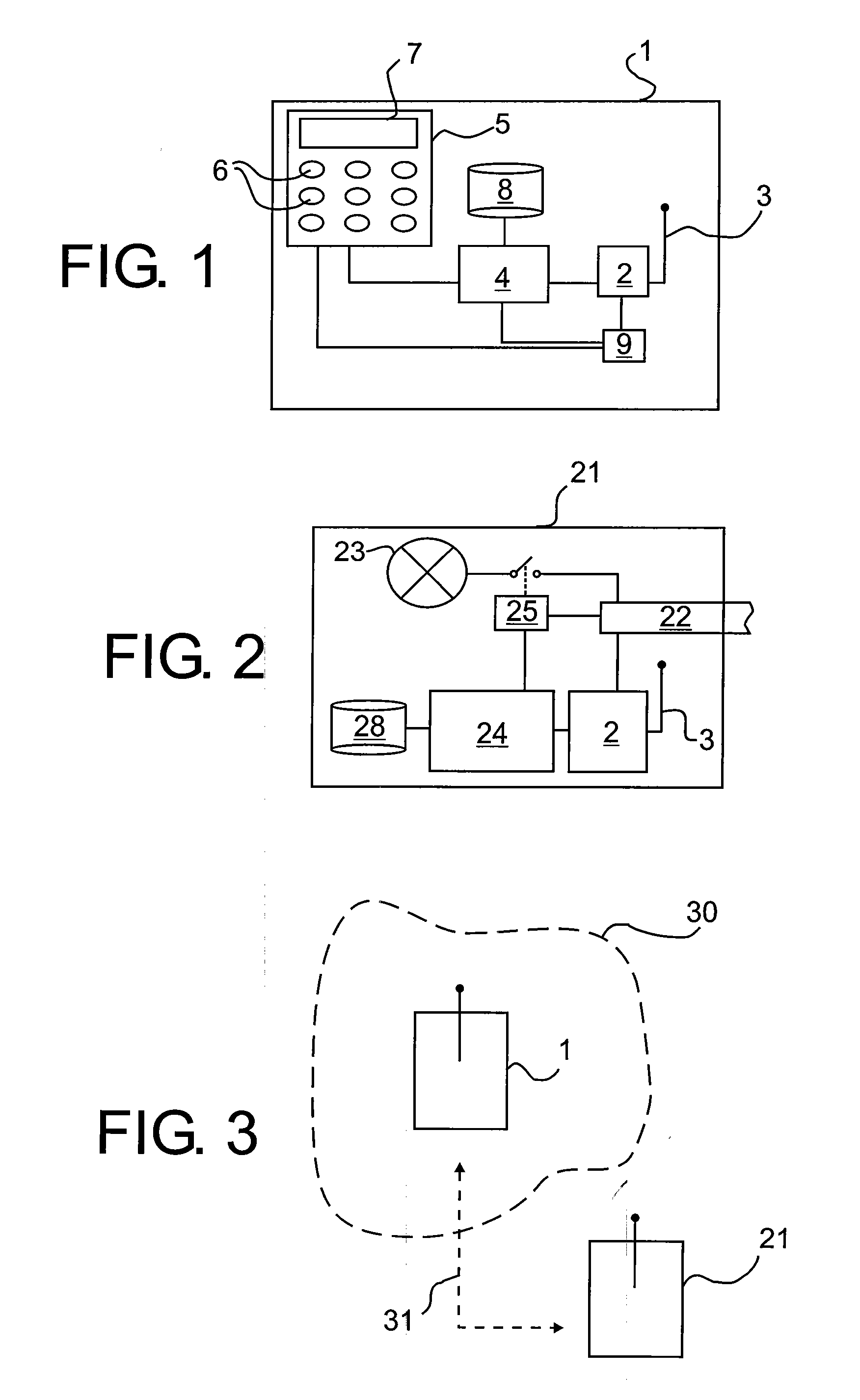
[0138]FIG. 1 shows a network device 1, in the present example a remote control device in a schematic representation. The network device 1 comprises a communication interface 2 with a suitable antenna 3, provided for radio-frequency wireless communication according to the Zigbee and IEEE 802.15.4 communication protocols, in the following referred to as ‘Zigbee’ or Zigbee protocol. IEEE 802.15.4 provides a physical link layer (PHY) and a media access control layer (MAC). Zigbee provides a network layer (NWK) and an application layer (APL) on top of the MAC-layer. A description of Zigbee and the Zigbee protocol stack is disclosed in the Zigbee specification, e.g. in document 053474r17, dated Oct. 19, 2007, available from the Zigbee Alliance Inc. As explained in the following, the communication interface 2 further implements the Zigbee Pro stack profile. An explanation of Zigbee Pro and a corresponding communications stack is disclosed in document 074855r05, dated January 2008, availabl...

eighth embodiment

[0221]In the present example, the joining device 111 is a lighting unit, which is shown in FIG. 12 in a schematic view according to an The joining device 21 comprises, correspondingly to the network device 1, a communication interface 2, provided for wireless RF-communication according to Zigbee. The communication interface 2 comprises a unique MAC-address for communication on the MAC-layer and is connected to a CPU 24, which controls the communication. The CPU 24 is connected to a device configuration memory 28 and an application interface 25, which is arranged to control a lamp 23, i.e. to switch the lamp 23 on and off and to dim the lamp 23. The application interface 25 is controllable over the network upon reception of an application control command from a remote control device, such as the network device 1. All components are connected to a power-supply unit 22, having a mains connection (not shown).

[0222]Further, a signal strength detector 80 is connected to the communication...


PUM


Abstract

A wireless network system (30, 60) and a method for commissioning a wireless network system (30, 60) is described. The network system (30, 60) comprises at least a network device (1, 1′, 1″) and a joining device (21, 81, 91, 101, 111). In a commissioning mode, the network device (1, 1′, 1″) broadcasts network identification information. The joining device (21, 81, 91, 101, 111) sends, upon reception of the network identification information, a request to said network device (1, 1′, 1″) to join the network, comprising a predefined address of said joining device (21, 81, 91, 101,111). The network device (1, 1′, 1″) assigns said joining device (21, 81, 91, 101, 111) a network address and stores corresponding data. The network device (1, 1′, 1″) sends joining information comprising at least said network address to said joining device (21, 81, 91, 101, 111) using said predefined address and said joining device (21, 81, 91, 101, 111) receives the network address, so that the joining device (21, 81, 91, 101, 111) is addressable in the network system (30, 60) using said network address.

Description

FIELD OF THE INVENTION[0001]The invention relates to a wireless network system and a method of commissioning a wireless network system.BACKGROUND OF THE INVENTION[0002]Wireless network systems with devices communicating over a wireless medium are today common for a variety of applications. Usually in such network systems, each device being part of the network has a distinguishable address, so that it is possible to direct messages to a specific device using this address. Each communication thus comprises in addition to the message at least an address, so that the message reaches its desired recipient. For example, in a network having remote control units and multiple controllable appliances, e.g. lighting devices, temperature sensors or heating devices, each of the remote control units needs information on how to address each single appliance to be able to control the appliances individually and in user-defined groups or to process received sensor values appropriately.[0003]To opera...

Claims


Application Information

Patent Timeline
IPC IPC(8): H04W40/00
CPCH04W8/005H04W48/12H04W8/26H04W8/02H05B47/105H05B47/19H05B47/195H04L61/5038H04L2101/681H05B47/199H04W84/18H04W48/10H04L41/12H04W84/12
Inventor MCCORMACK, JAMES JOSEPH ANTHONYSCHEPERS, HENDRIK JAN JOZEF HUBERTUS
Owner KONINKLIJKE PHILIPS ELECTRONICS NV
Features
  • Generate Ideas
  • Intellectual Property
  • Life Sciences
  • Materials
  • Tech Scout
  • Unparalleled Data Quality
  • Higher Quality Content
  • 60% Fewer Hallucinations
Learn More