Bearing installation structure and installation method

a technology of installation structure and bearing, which is applied in the direction of engine components, mechanical equipment, manufacturing tools, etc., can solve the problems of reducing the operation rate of the production line, affecting the service life of the bearing, so as to reduce damage, prevent a tightening load, and facilitate torque management

Inactive Publication Date: 2011-06-23
HONDA MOTOR CO LTD
View PDF6 Cites 5 Cited by
  • Summary
  • Abstract
  • Description
  • Claims
  • Application Information

AI Technical Summary

Benefits of technology

[0015]According to the present invention, it is possible to make a structure for which torque management is easy, since the torque from tightening can be simply calculated by measuring a compression amount of the conical spring such as a dimension of the conical spring that changes from tightening, or the like. In addition, since the biasing force generated by the conical spring is constant after tightening, it is possible to prevent a tightening load above a specified amount from acting on the bearing by managing the dimension of the conical spring, which changes by compression. Furthermore, since pretension management can be performed simply by tightening so that the height of the conical spring is a constant dimension, a technician that performs maintenance in a production line in which welding guns including bearings are provided can easily perform manage the bearings at the pretension amount that had been specified, without requiring special tools.
[0016]According to the present invention, it is possible to reduce damage, while making operation and maintenance on bearings supporting a fulcrum shaft that pivotally supports a gun arm easy.

Problems solved by technology

However, torque management of the pretension force imparted to this pretension structure requires special tools such as a torque wrench.
As a result, when a tightening load higher than prescribed is applied to a bearing as a result of imparting a pretension force by using a regular tightening tool such as a spanner, an excessive load may be applied to a casting, which is a structure having the bearing installed therein, and cause the casting to be damaged.
In addition, the bearing service life may be considerably reduced as a result of applying a pretension force higher than prescribed to the bearing.
The above fact may cause the operation and maintenance for maintaining bearings to be complicated, as well as a production line employing machines provided with bearings to be stopping due to operation and maintenance or repair of damage, thereby inviting a decline in the rate of operation of the production line.

Method used


Image

  • Bearing installation structure and installation method
  • Bearing installation structure and installation method
  • Bearing installation structure and installation method

Examples


Embodiment Construction

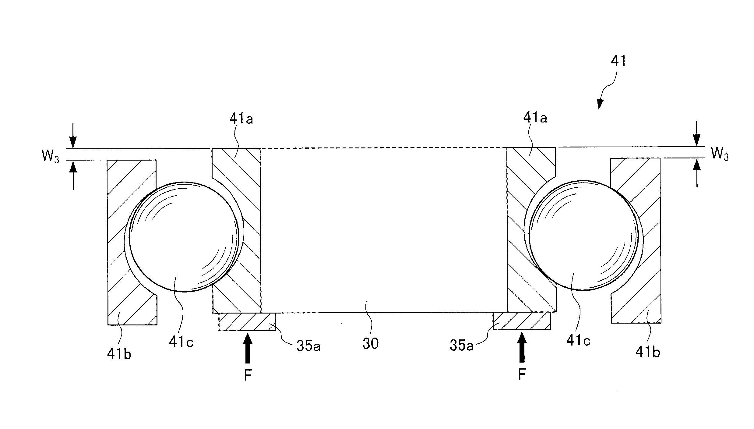
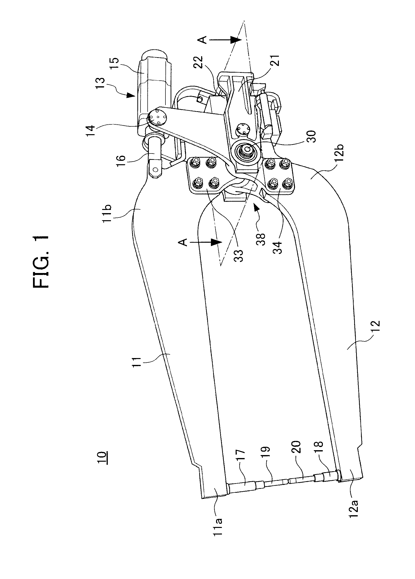
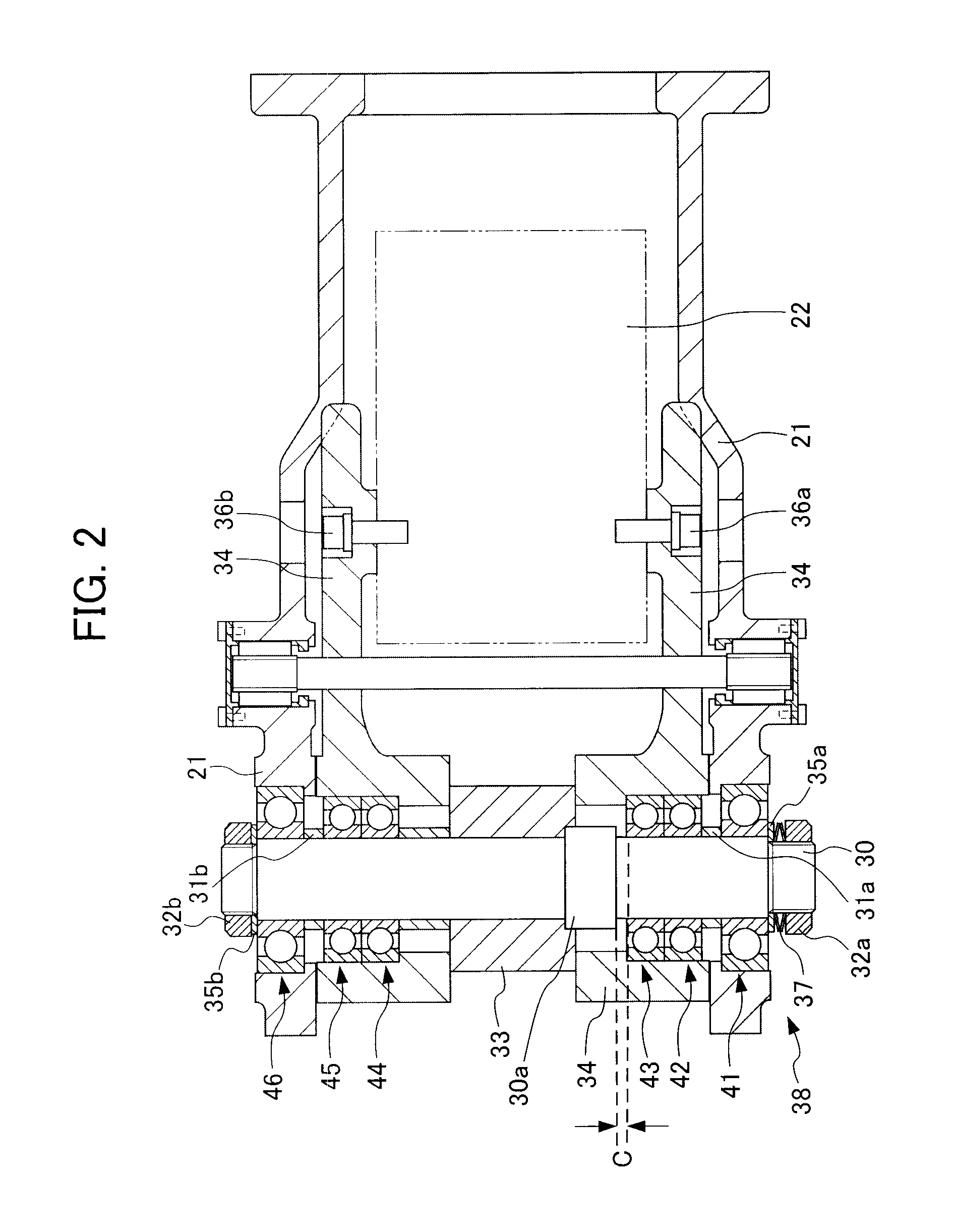
[0022]FIG. 1 is a three-dimensional side view of a welding gun 10 provided with bearings installed as an installation structure 38 of bearings according to an embodiment of the present invention. The welding gun 10 shown in FIG. 1 is used to be mounted on a leading end of a robot arm and designed to pivotally support an upper and lower pair of gun arm, which are constituted by a first gun arm 11 and a second gun arm 12 that open and close by way of an pneumatic cylinder 13, at a fulcrum shaft 30 provided at a leading end of a gun bracket 21 attached to the leading end of the arm of the robot that is not illustrated. Furthermore, the welding gun 10 is adapted to move a plurality of spot positions on a work (not illustrated) sequentially and perform welding, as described below. As shown in FIG. 2, the gun arms are pivotally supported by a plurality of bearings including a first bearing 41, a second bearing 42, a third bearing 43, a fourth bearing 44, a fifth bearing 45 and a sixth bea...


PUM

PropertyMeasurementUnit
rigidityaaaaaaaaaa
constant pressureaaaaaaaaaa
torqueaaaaaaaaaa

Abstract

An installation structure of bearings and an installation method are provided that can reduce the amount of damage caused by tightening bearings supporting a fulcrum shaft that pivotally supports a gun arm, as well as simplify operation and maintenance. One race is fixed among an inner race and an outer race constituting a bearing, which supports a fulcrum shaft (30) pivotally supporting a first gun arm (11) and a second gun arm (12) constituting a welding gun (10) to be rotatable, and relates to an installation structure (38) of bearings that receive a combined load of an axial load acting in an axial direction of the fulcrum shaft (30) and a radial load acting in a radial direction thereof. The other race among the inner race and outer race constituting the bearing is installed in the radial direction to be movable in a direction in which there is no longer a radial gap or axial gap between the inner race, outer race and a revolving body disposed between the outer race and the inner race to revolve freely.

Description

[0001]This application is based on and claims the benefit of priority from Japanese Patent Application No. 2009-289513, filed on 21 Dec. 2009, the content of which is incorporated herein by reference.BACKGROUND OF THE INVENTION[0002]1. Field of the Invention[0003]The present invention relates to an installation structure of bearings supporting a fulcrum shaft that pivotally supports a gun arm, and an installation method thereof. More specifically, the present invention relates to an installation structure of bearings that reduces the damage occurring due to tightening bearings, and makes operation and maintenance easy.[0004]2. Related Art[0005]Conventionally, roller bearings have been used as bearings supporting a fulcrum shaft for pivotally supporting gun arms of an X-type welding gun provided with electrode tips at the leading ends thereof (e.g., refer to Japanese Unexamined Patent. Application Publication No. 2002-178160). In such gun arms, pretension is applied to the bearings s...

Claims


Application Information

Patent Timeline
Patent Type & Authority Applications(United States)
IPC IPC(8): F16C33/58B21D53/10
CPCB23K11/314Y10T29/49682F16C25/083B23K11/36
Inventor MATSUMOTO, KOICHIKOBAYASHI, TERUAKIMIWA, HIROSHI
Owner HONDA MOTOR CO LTD
Why Eureka
Try Eureka