
Prepreg, intermediate material for forming frp, and method for production thereof and method for production of fiber-reinforced composite material

a technology of intermediate materials and composite materials, which is applied in the direction of synthetic resin layered products, applications, weaving, etc., can solve the problems of ineffective inability to produce larger products, limited size of molded products, and high cost of autoclave facilities, so as to improve the specific strength and inelasticity, reduce the viscosity of resin, and improve the effect of cost performan

Inactive Publication Date: 2011-06-23
MITSUBISHI RAYON CO LTD
View PDF27 Cites 9 Cited by
  • Summary
  • Abstract
  • Description
  • Claims
  • Application Information

AI Technical Summary

Benefits of technology

[0041]The quantity of the thermoplastic resin within the thermosetting resin composition is preferably within a range of 1 to 100 parts by mass per 100 parts by mass of the thermosetting resin composition. If the quantity of the thermoplastic resin is less than 1 part by mass, then the effect of the invention in improving the FRP interlayer peeling resistance weakens undesirably. Quantities of the thermoplastic resin of at least 5 parts by mass are even more desirable, and quantities of at least 10 parts by mass are particularly preferred. In contrast, if the quantity exceeds 100 parts by mass, then the proportion of the thermoplastic resin becomes overly high, which can cause a deterioration in the impregnation of the matrix resin into the sheet-like reinforcing fiber substrate, and the quantity of the matrix resin relative to the sheet-like reinforcing fiber substrate can become too high, causing an undesirable deterioration in the FRP mechanical strength.
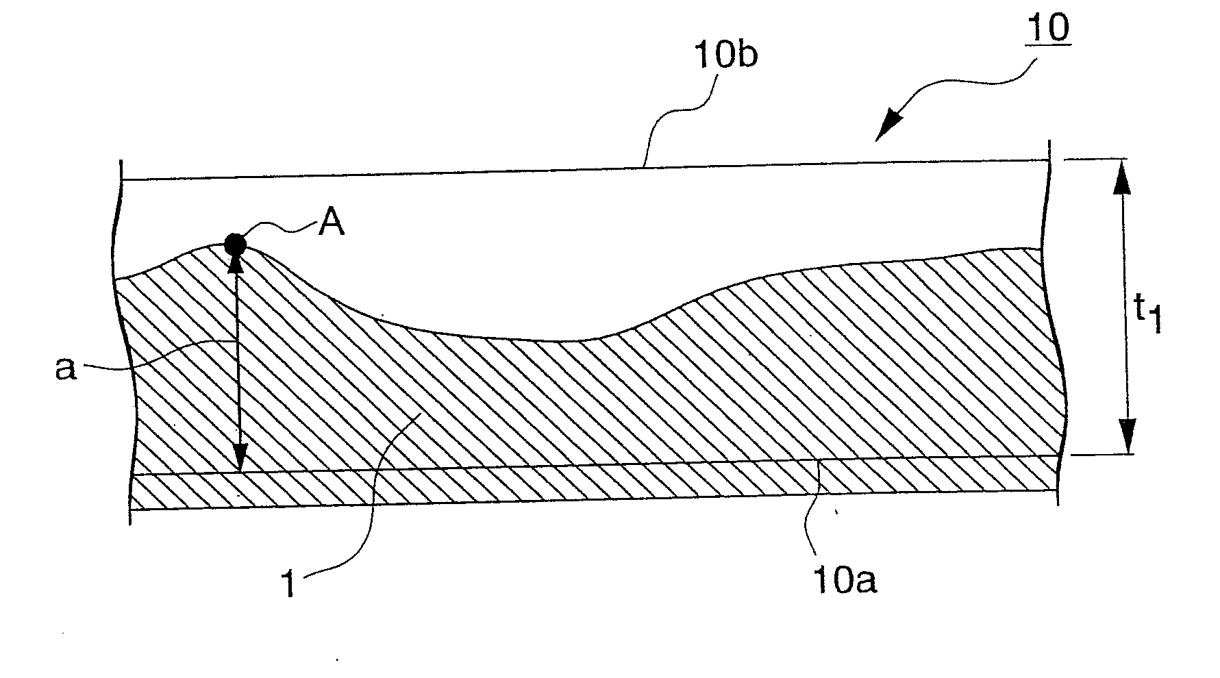
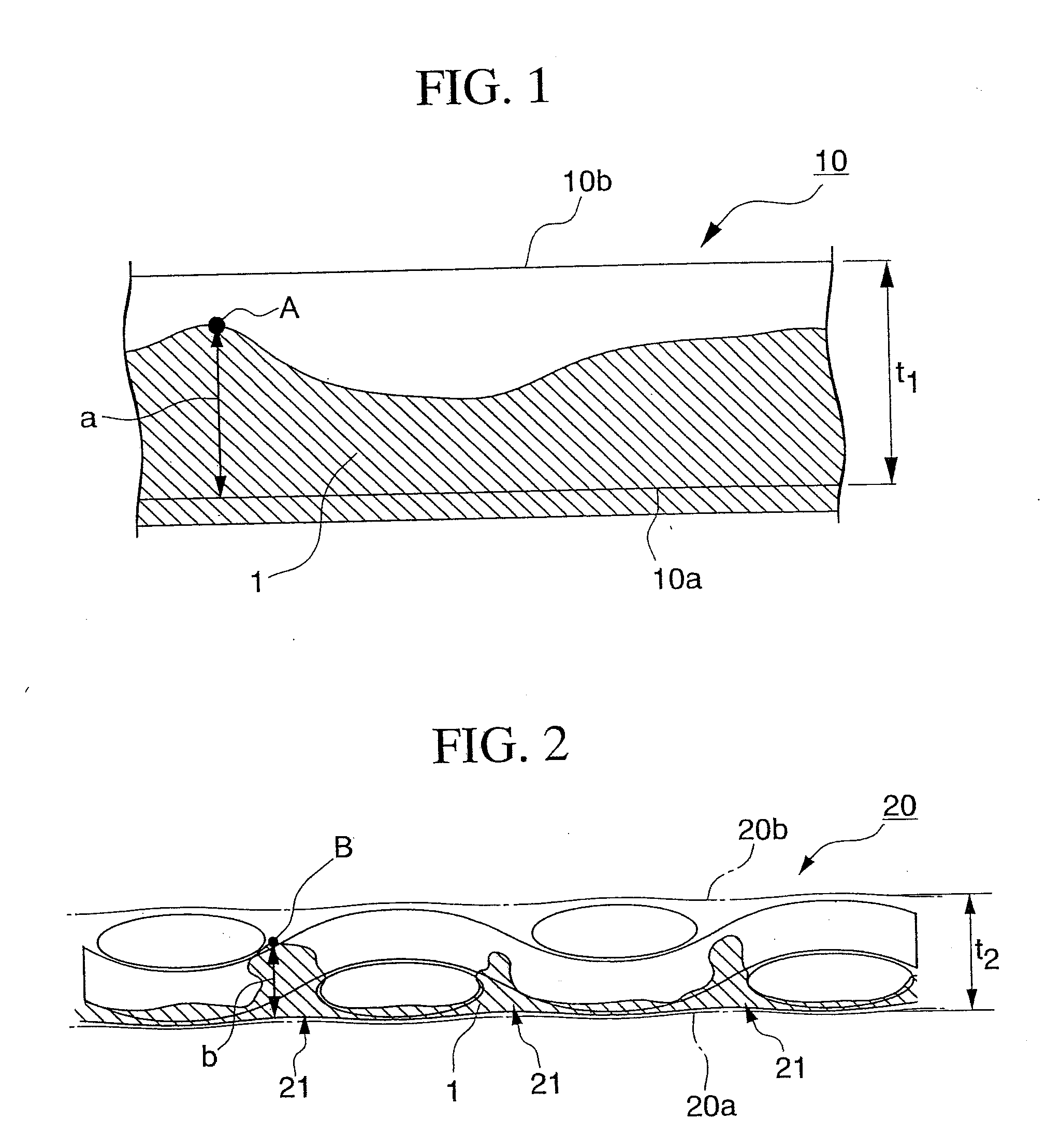
[0042]Although there are no particular restrictions on the process for producing a prepreg according to the first embodiment, a production process in which a resin is supplied, using a hot melt method, to one surface of a sheet-like reinforcing fiber substrate comprising reinforcing fibers, and the structure is then heating and pressed, causing the resin to migrate through to a position close to the opposite surface of the substrate is preferred. In such a process, the heating temperature and the pressure applied during the pressing step are adjusted to control the degree of migration of the resin and the manner of the migration, thus adjusting the resin impregnation ratio to a value within a range of 35% to 95%. The hot melt method is a prepreg production process in which no solvent is used, and the viscosity of the resin is lowered by raising the temperature of the resin, thereby causing the resin to impregnate the substrate, and amongst the possible forms of the hot melt method that can be used for producing a prepreg, a double film process, in which the resin is supplied from both the upper and lower surfaces of the sheet-like reinforcing fiber substrate is usually preferred in terms of the impregnation results. However, in the first embodiment, because one surface of the prepreg must be available for forming the deaerating circuit and can therefore not be impregnated with resin, the double film process is not suitable as the process for producing a prepreg according to the first embodiment. As described above, a single film process in which the resin is supplied from one surface of the sheet-like reinforcing fiber substrate is preferred.
[0043]The matrix resin in a prepreg of the first embodiment is a thermosetting resin composition, and in those cases where the composition also comprises a thermoplastic resin that has not been dissolved in the thermosetting resin composition, the thermoplastic resin is preferably blended into the composition during the mixing and preparation of the thermosetting resin composition, and the resulting composition is then converted to a film form, and impregnated into the sheet-like reinforcing fiber substrate.
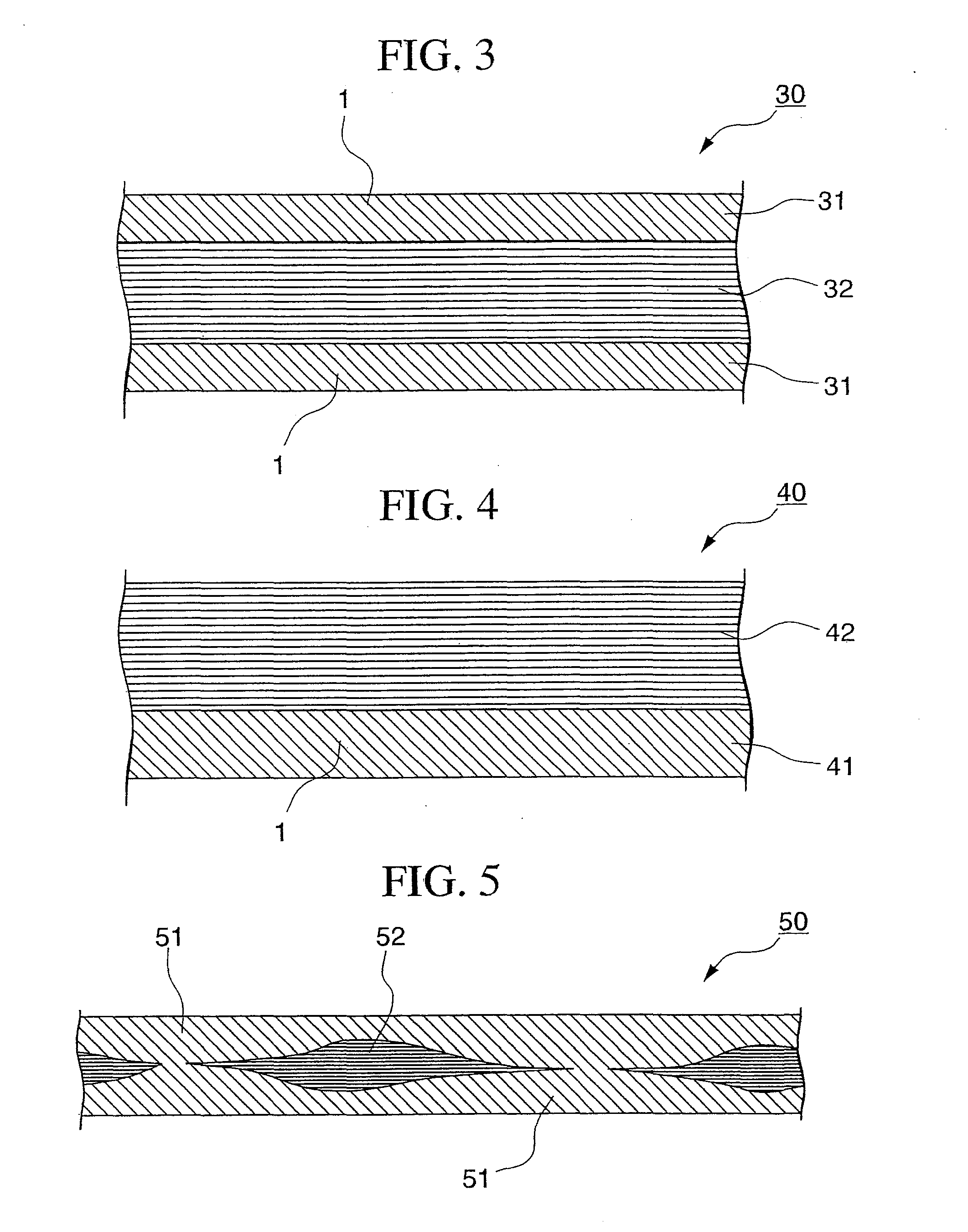
[0044]A second embodiment of the present invention is a prepreg comprising a sheet-like reinforcing fiber substrate and a matrix resin, wherein the matrix resin exists on both surfaces of the sheet-like reinforcing fiber substrate, and the portion inside the sheet-like reinforcing fiber substrate into which the matrix resin has not been impregnated is continuous.
[0045]There are no particular restrictions on the reinforcing fibers used in the sheet-like reinforcing fiber substrate used in a prepreg of this second embodiment, and examples of suitable fibers include carbon fiber, graphite fiber, aramid fiber, silicon carbide fiber, alumina fiber, boron fiber, high-strength polyethylene fiber, PBO fiber, and glass fiber, and these fibers can be used either singularly, or in mixtures of two or more different types of fiber. Of these reinforcing fibers, either carbon fiber which offers superior specific strength and inelasticity, or glass fiber which offers more favorable cost performance, is preferred.
[0046]Furthermore, there are also no particular restrictions on the form of the sheet-like reinforcing fiber substrate used in the prepreg of this second embodiment, and suitable examples include unidirectional materials in which the reinforcing fibers are aligned unidirectionally, woven fabrics, knit fabrics, braided fabrics, stitched sheets wherein multiple fabrics are laminated, either unidirectionally or in various directions, and then stitched, as well as mats and non-woven fabrics comprising short fibers. Of these, woven fabrics, stitched sheets, mats and non-woven fabrics offer superior levels of stability for the sheet-like reinforcing fiber substrate, and because an intermediate material for FRP molding of the present invention offers superior handling properties, it is preferred as the sheet-like reinforcing fiber substrate.

Problems solved by technology

However, autoclave facilities are extremely expensive, which not only acts as a large barrier to new entrants, but also means that once autoclave facilities are purchased, the size of the molded products is restricted by the size of the autoclave, meaning the production of larger products is effectively impossible.
However, because these processes do not involve the application of pressure, residual voids tend to remain within the molded product, the strength of the molded product is inferior to that of a molded product produced in an autoclave, and pinhole formation is also a problem.
However, with this technology, almost all of the resin is impregnated during molding, and depending on the molding conditions, portions of the resin that display unsatisfactory impregnation can occur, leading to the occurrence of internal voids and surface pinholes.
Furthermore, because the surface is almost free from resin and is extremely dry, workability problems such as difficulty in bonding the product to the molding die can also be a concern.

Method used


Image

  • Prepreg, intermediate material for forming frp, and method for production thereof and method for production of fiber-reinforced composite material
  • Prepreg, intermediate material for forming frp, and method for production thereof and method for production of fiber-reinforced composite material
  • Prepreg, intermediate material for forming frp, and method for production thereof and method for production of fiber-reinforced composite material

Examples


example 1

[0140]The matrix resin was applied uniformly to a release sheet at a resin weight of 430 g / m2, thus forming a resin film. This resin film was supplied to a piece of carbon fiber cloth TRK510, manufactured by Mitsubishi Rayon Co., Ltd. (fiber weight 646 g / m2, 2 / 2 twill) from the bottom surface of the cloth, thus impregnating the carbon fiber cloth with the resin. The temperature during impregnation was 60° C., and the pressure was adjusted to complete the preparation of a prepreg. When the resin impregnation ratio of the thus produced prepreg was measured, the result was 90%, thus confirming the prepreg as conforming to the present invention.

[0141]Next, using the release sheet side of the thus produced prepreg of the present invention as the tool side (a stainless steel plate), a 4-ply laminate was formed at 0° C. The layers from the second layer up were arranged so that the release sheet side of the prepreg faced the opposite side of the previous layer. Vacuum bag molding was conduc...

example 4

[0150]An epoxy resin composition #830 manufactured by Mitsubishi Rayon Co., Ltd. was used as the matrix resin. Using this resin, a resin film was prepared in the same manner as the example 1, and this was then impregnated into a TRK510. The impregnation temperature was set to 50° C. When the resin impregnation ratio of the thus obtained prepreg was measured, the result was 60%, thus confirming the prepreg as conforming to the present invention. Using this prepreg, a molded product of the shape shown in FIG. 3 was molded. A wooden female mold was used as the molding die. An 8-ply laminate was formed using an alignment pattern of [0° / 45° / 90° / −45° / −45° / 90° / 45° / 0°], with the release sheet side of the prepreg facing the tool surface, and subsequently prepregs arranged so that the release sheet side faced the opposite side of the previous layer. The operation of laminating the prepregs presented absolutely no problems.

[0151]Under the molding conditions used, the temperature was raised fro...

example 5

[0153]Using the resin used in the example 1, and using a non-crimped fabric Quadraxial-Carbon-Gelege (+45°: Carbon 267 g / m2, 0°: Carbon 268 g / m2, −45°: Carbon 267 g / m2, 90°: Carbon 268 g / m2, stitching: PES 6 g·m2, weight 1076 g / m2) manufactured by Saertex Co., Ltd. as a sheet-like reinforcing fiber substrate, a prepreg was prepared in the same manner as the example 1. However, the resin weighting was 717 g / m2. When the resin impregnation ratio was measured, the result was 75%, thus confirming the prepreg as conforming to the present invention. A 2-ply laminate was prepared with the prepreg surfaces facing in the same direction, and a FRP was then molded. The molding was conducted under the same molding conditions as the example 1. The thus obtained molded product displayed no internal voids and no surface pinholes.


PUM

PropertyMeasurementUnit
lengthaaaaaaaaaa
lengthaaaaaaaaaa
lengthaaaaaaaaaa

Abstract

An FRP is produced using a prepreg comprising reinforcing fiber, a sheet-like reinforcing fiber substrate containing reinforcing fiber, and a matrix resin, wherein the matrix resin is impregnated into the sheet-like reinforcing fiber substrate and also covers one surface of the sheet-like reinforcing fiber substrate, and the matrix resin impregnation ratio is within a range of 35% to 95%; a prepreg comprising reinforcing fiber, a sheet-like reinforcing fiber substrate containing reinforcing fiber, and a matrix resin, wherein the matrix resin exists on both surfaces of the sheet-like reinforcing fiber substrate, and the portion inside the sheet-like reinforcing fiber substrate into which the matrix resin has not been impregnated is continuous; or a prepreg comprising reinforcing fiber, a sheet-like reinforcing fiber substrate containing reinforcing fiber, and a matrix resin, wherein at least one surface exhibits a sea-and-island-type pattern comprising resin-impregnated portions (island portions) where the matrix resin is present at the surface and fiber portions (sea portions) where the matrix resin is not present at the surface, the surface coverage ratio of the matrix resin on those surfaces with said a sea-and-island-type pattern is within a range of 3% to 80%, and the weave intersection coverage ratio for the island portions, represented by a formula (1) shown below, is at least 40%, displays excellent external appearance, with no internal voids or surface pinholes, even when molded is conducted using only vacuum pressure.Island portions weave intersection coverage ratio (%)=(T / Y)×100  (1)(wherein, T represents a number of island portions that cover weave intersections, and Y represents a number of weave intersections within said reinforcing fiber woven fabric on said surface with said sea-and-island-type pattern).

Description

TECHNICAL FIELD[0001]The present invention relates to a prepreg that functions as an intermediate material for FRP molding.BACKGROUND ART[0002]Fiber-reinforced composite materials (hereafter also abbreviated as FRP) are lightweight, while offering good strength and high rigidity, and are consequently widely used in a variety of applications from sports and leisure through to industrial applications such as vehicles and aircraft. In recent years, with the fall in the cost of carbon fiber, the use of carbon fiber reinforced composite materials (hereafter abbreviated as CFRP), which are even more lightweight and offer even higher levels of strength and rigidity, within industrial applications has also become more widespread.[0003]Amongst these potential industrial applications, CFRPs used for structural members within train bodies and aircraft frames are typically produced by autoclave molding, using an intermediate material known as a prepreg. The reason for this preference is that by...

Claims


Application Information

Patent Timeline
Patent Type & Authority Applications(United States)
IPC IPC(8): B32B5/02B32B37/00B32B3/10B32B7/02B32B27/04B29C70/44B29C70/46B29C70/54
CPCB29B15/122Y10T428/2495B29C70/086B29C70/22B29C70/342B29C70/465B29C70/546B29K2063/00B29K2101/10B29K2101/12B32B5/022B32B5/26C08J5/24B32B2260/023B32B2262/106B32B2305/076B32B2363/00D06M15/55Y10T156/10Y10T428/2481B29C70/081Y10T428/249921Y10T442/2861Y10T442/2951Y10T442/2992Y10T442/20Y10T442/2984Y10T442/2361Y10T442/2139Y10T442/2926Y10T442/3854Y10T442/2008Y10T442/2049C08J5/243
Inventor GOTO, KAZUYAKOGA, KAZUKISAITOU, TADAYOSHIITO, AKIHIROTAKANO, TSUNEOWAKABAYASHI, KOUKI
Owner MITSUBISHI RAYON CO LTD
Learn More