Superconducting cable

Inactive Publication Date: 2011-06-23
NE
View PDF10 Cites 0 Cited by
  • Summary
  • Abstract
  • Description
  • Claims
  • Application Information

AI Technical Summary

Benefits of technology

[0009]The invention is based on the object of developing the cable described initially such that it can be produced more easily, with a simpler design.
[0011]In this cable, the central conductor, which can be considered to be a superconducting forward conductor, consists of a single-layer tube which is formed, running longitudinally, from a ribbon to which the superconducting material is fitted. The tube is intrinsically sufficiently robust that no separate support is required for the central conductor. This itself consists only of one layer, which is governed by the thickness of the ribbon, thus allowing its radial dimensions to be kept small. This has an advantageous effect on the radial dimensions of the dielectric, which can be made smaller overall in comparison to known cables. The ribbon which surrounds the conductor and is composed of semiconductive material makes the conductor robust and avoids dielectric problems which could occur as a result of the edges that exist adjacent to the slot of the conductor. Including the return conductor, this results overall in a compact superconducting cable with relatively small radial dimensions, and correspondingly using less material. The dimensions of the cryostat which holds the cable can advantageously likewise be kept smaller than normal.
[0012]The return conductor can advantageously likewise be formed from a longitudinally running, ribbon, fitted with superconducting material, to form a single-layer tube. When the same is in the form of a closed tube, as a result of the welding of the slot running in the longitudinal direction, this achieves a further advantage of effective separation of the dielectric from coolant which is moving in the cryostat outside the return conductor. The pressure of an impregnation agent which is provided in the dielectric can thus be kept constant in a simple manner—independently of the pressure of the coolant—as a result of which the dielectric characteristics of the dielectric also remain constant.

Problems solved by technology

The production of this known cable is complex.

Method used


Image

  • Superconducting cable
  • Superconducting cable

Examples


Embodiment Construction

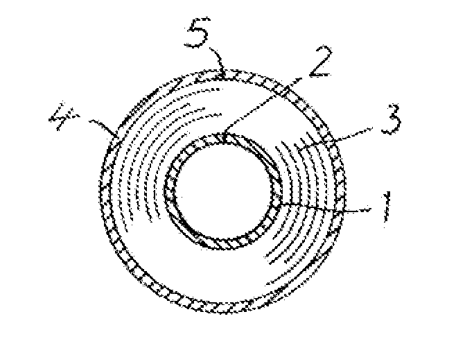
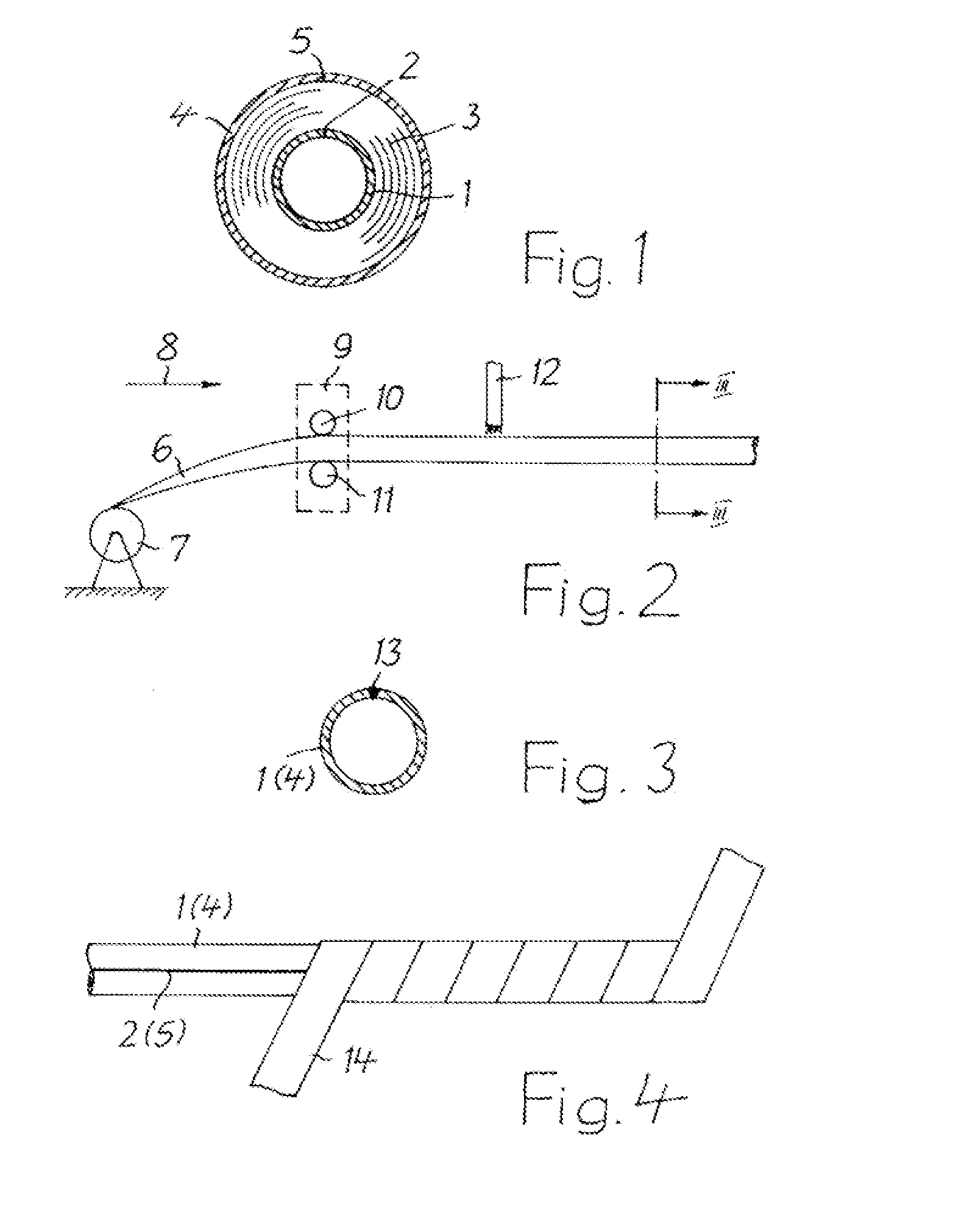
[0019]The superconducting cable illustrated in the form of a section in FIG. 1 has a central conductor (forward conductor) 1 in the form of a single-layer tube. The conductor 1 is formed from a longitudinal running ribbon of predetermined width, which is fitted with superconducting material, to form a tube with a slot 2 which runs in the longitudinal direction and on which the two edges of the ribbon rest on one another. ReBCO is preferably used, and particularly advantageously YRCO, as the superconducting material. In order to make it robust, the conductor 1 is surrounded by a ribbon 14, which can be seen in FIG. 4, composed of semiconductive material, at least one layer of which is wound around the conductor 1. The ribbon 14 is not shown in FIG. 1, for the sake of clarity.

[0020]A dielectric 3 which is known per se and is surrounded by a superconducting return conductor 4 is arranged over the conductor 1, or over the ribbon 14 which is wound around it. The return conductor 4 may it...


PUM


Abstract

A superconductive cable with a central superconductive conductor (1), a surrounding dielectric (3) and a surrounding superconductive return conductor (4). The central conductor (1) is formed from a single ribbon carrying superconductive material into a tube with a longitudinal extending slot (2) with the two edges of the ribbon abutting to each other. A ribbon (14) made of semiconductive material is wound around the central conductor (1) with at least one layer.

Description

RELATED APPLICATION[0001]This application claims the benefit of priority from Euopean Patent Application No. 09 306 154.7, filed on Nov. 30, 2009, the entirty of which is incorporated by reference.BACKGROUND[0002]1. Field of the Invention[0003]The invention relates to a superconducting cable which has a central superconducting electrical conductor, a dielectric which surrounds the same and a superconducting return conductor which is arranged above the same.[0004]2. Description of Related Art[0005]A cable such as this is disclosed in EP 0 830 694 B1.[0006]In modern technology, a superconducting cable has electrical conductors composed of a composite material which contains ceramic material that changes to the superconducting state at sufficiently low temperatures. The electrical direct-current resistance of a correspondingly constructed conductor is zero, if the coolant is adequate, provided that a specific current level is not exceeded. By way of example, suitable ceramic materials ...

Claims


Application Information

Patent Timeline
IPC IPC(8): H01B12/10H01B12/00
CPCY02E40/641H01B12/12Y02E40/60
Inventor SCHMIDT, FRANK
Owner NE
Why Eureka
Try Eureka