Implantable device

a technology of implantable devices and proximal arteries, which is applied in the direction of tubular organ implants, prostheses, blood vessels, etc., can solve the problems of narrowing of the arteries inside the skull and the delicate arteries of the brain, and achieve the effects of reducing longitudinal stiffness, maintaining radial stiffness, and secure anchoring of the implant within the vessel

Inactive Publication Date: 2011-06-23
COOK MEDICAL TECH LLC
View PDF11 Cites 30 Cited by
  • Summary
  • Abstract
  • Description
  • Claims
  • Application Information

AI Technical Summary

Benefits of technology

[0009]Providing a relatively soft zone having a reduced longitudinal stiffness allows the implant to conform more easily to curvature within a tortuous vessel. By flanking the relatively soft zone by relatively stiffer zones, improved security of positioning of the implant within the vessel can be achieved.
[0011]In an embodiment the stent includes a plurality of stent rings connected to each other by tie bars. The relatively soft zone may include relatively soft tie bars and relatively stiff stent rings. This is a preferred way of allowing reduced longitudinal stiffness whilst maintaining radial stiffness.
[0012]Preferably a relatively soft zone is located in a substantially central region of the implant. By maintaining longitudinal stiffness towards the ends of the implant, more secure anchoring of the implant within a vessel can be obtained.
[0014]In the preferred embodiment, the implant is a stent including a plurality of stent rings connected to each other longitudinally by tie bars, wherein the tie bars of the relatively soft zone have a transition temperature above normal body temperature, and wherein the stent ring or stent rings of the relatively soft zone have a transition temperature below normal body temperature. This allows reduced longitudinal stiffness within the relatively soft zone whilst maintaining radial stiffness.
[0016]A relatively stiffer zone may be located at each end of the implant. This assists with secure positioning of the implant within a vessel. Each relatively stiffer zone preferably includes at least two stent rings. In an embodiment, each relatively stiffer zone may include up to five stent rings, for example.

Problems solved by technology

Narrowing of the arteries inside the skull is a significant cause of stroke.
The arteries of the brain are particularly delicate, and tend to be considerably more tortuous than the vasculature elsewhere in the body.

Method used


Image

  • Implantable device
  • Implantable device
  • Implantable device

Examples


Embodiment Construction

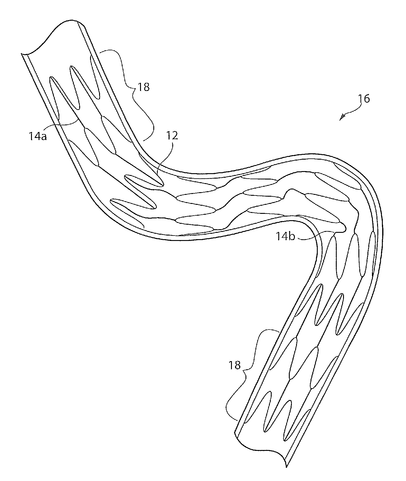
[0026]It is to be understood that the Figures are schematic and do not show the various components to their actual scale. In many instances, the Figures show scaled up components to assist the reader.

[0027]In this description, when referring to an introducer or a deployment assembly, the term distal is used to refer to an end of a component which in use is furthest from the surgeon during the medical procedure, including within a patient. The term proximal is used to refer to an end of a component closest to the surgeon and in practice in or adjacent an external manipulation part of the deployment or treatment apparatus.

[0028]On the other hand, when referring to an implant such as a stent or stent graft, the term proximal refers to a location that in use is closest to the patient's heart, in the case of a vascular implant, and the term distal refers to a location furthest from the patient's heart.

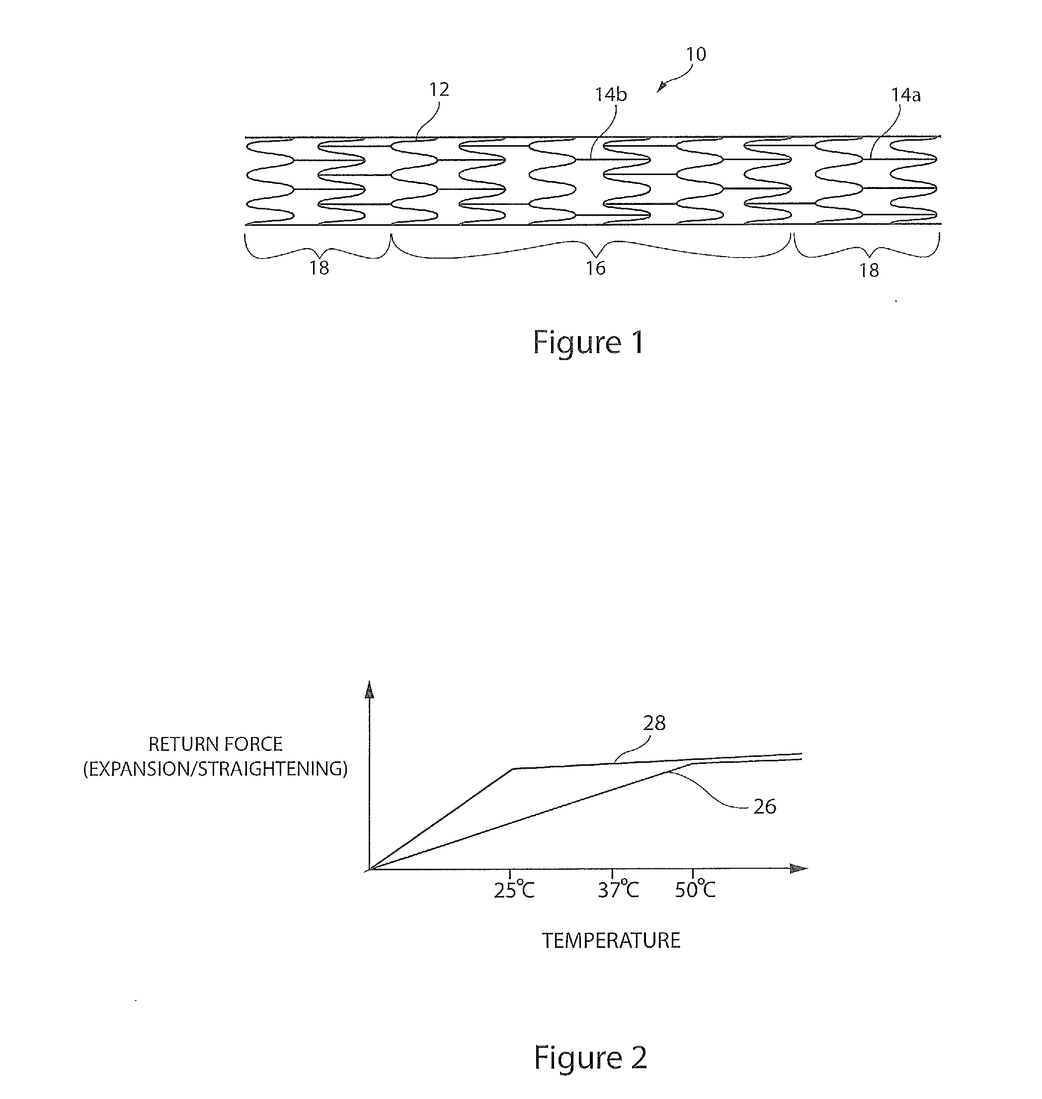
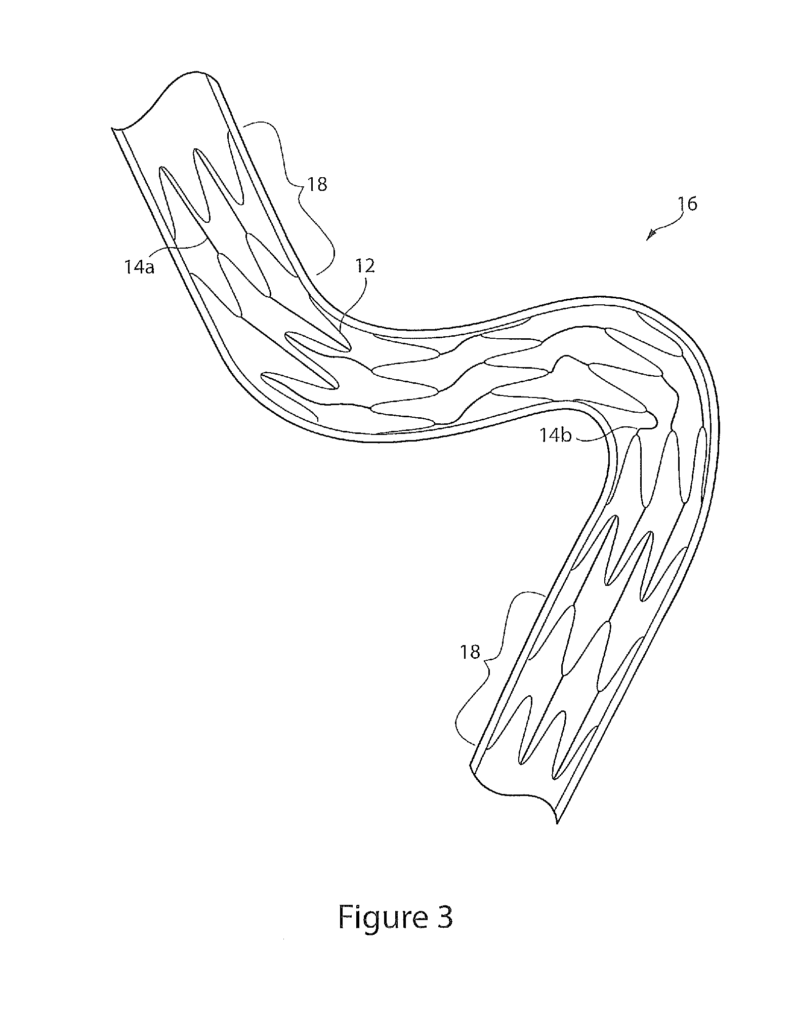
[0029]FIG. 1 illustrates an intracranial stent in accordance with a preferred embodimen...


PUM

PropertyMeasurementUnit
transition temperatureaaaaaaaaaa

Abstract

An intracranial stent formed from Nitinol has variable flexibility. The stent (10) is formed from a plurality of stent rings (12) connected by tie bars (14). The tie bars (14) in a central soft zone (16) are heat treated so as to confer a higher transition temperature on the Nitinol. As a result, at body temperature, the soft zone (16) has reduced longitudinal stiffness as compared to the stiffer zones (18) found at the ends of the stent (10).

Description

TECHNICAL FIELD[0001]The present application relates to an implantable device, such as a stent, in particular for use as an intracranial implant or in other delicate vessels and organs. It also relates to an introducer or catheter assembly including an implantable device as taught herein.BACKGROUND OF THE INVENTION[0002]Stents are used for treatment of vasculature in the human or animal body normally to prevent or counteract an illness or a disease-induced localised flow constriction. Surgical stents have long been known which can be surgically implanted into a body lumen, such as in an artery, to reinforce, support, repair or otherwise enhance the performance of the lumen. For instance, in cardiovascular surgery it is often desirable to place a stent in the coronary artery at a location where the artery is damaged or is susceptible to collapse. The stent, once in place, reinforces that portion of the artery allowing normal blood flow to occur through the artery. One form of stent w...

Claims


Application Information

Patent Timeline
Patent Type & Authority Applications(United States)
IPC IPC(8): A61F2/84A61F2/82C22C14/00A61F2/91A61F2/915A61F2/966
CPCA61F2/91A61F2/915A61F2/966A61F2002/9155A61F2230/0054A61F2002/91575A61F2250/0018A61F2250/0029A61F2250/0042A61F2002/91558
Inventor HENDRIKSEN, PERHANSEN, PALLE M.
Owner COOK MEDICAL TECH LLC
Why Eureka
Try Eureka