Delivery system for multiple stents

a delivery system and stent technology, applied in the field of multiple stent delivery systems, can solve the problems of increasing radial compression, permanent deformation and/or fatigue failure, and achieving the effect of preventing undesirable axial movements

Inactive Publication Date: 2011-06-23
TRINITY COLLEGE DUBLIN
View PDF9 Cites 16 Cited by
  • Summary
  • Abstract
  • Description
  • Claims
  • Application Information

AI Technical Summary

Benefits of technology

[0082]The formations on the balloon may prevent the undesirable axial movements of stent segments.
[0083]In one case of the interlinked or interlocked stent segments the formations prevent the undesirable displacement of the terminal segments, and by virtue of the fact that the multiple stents are interlocked until near the end of the expansion process, the formations in this case control the displacements of every stent segment on the balloon.

Problems solved by technology

Many stents developed for the peripheral vessels were based on platforms designed for coronary applications and were not designed with the unique operating environment of peripheral arteries in mind.
Simultaneously, the relatively large diameters of peripheral vessels requiring stenting will mean a thicker vessel wall causing increased radial compression.
In terms of contemporary stent designs, this has proven difficult to achieve, requiring a trade-off between stent flexibility and wall support.
However, they are not used in peripheral arteries as many of these arteries are subjected to a more extreme mechanical environment (i.e vessel bending due to joint flexion and extension, muscular forces etc.) than coronary arteries.
Highly rigid balloon expandable stents tend to cause significant injury when implanted into such arteries, and tend to become permanently deformed and / or subject to fatigue failure.
However self-expanding stents provide less support and reliability in situ than classical balloon inflatable stents, not to mention less controllability during implantation.
Generally, self-expanding stents are a less popular tool amongst interventional cardiologists.
In these methods the stent movement on the balloon is generally limited to using friction or barriers.
Due to the expansion and unfolding of a stent delivery angioplasty balloon during inflation, the stents tend to rotate during the deployment due to friction between the balloon and stent.
This rotation of stent segments is undesirable as it can change the position of the multiple stent segments with respect to each other.

Method used


Image

  • Delivery system for multiple stents
  • Delivery system for multiple stents
  • Delivery system for multiple stents

Examples


Embodiment Construction

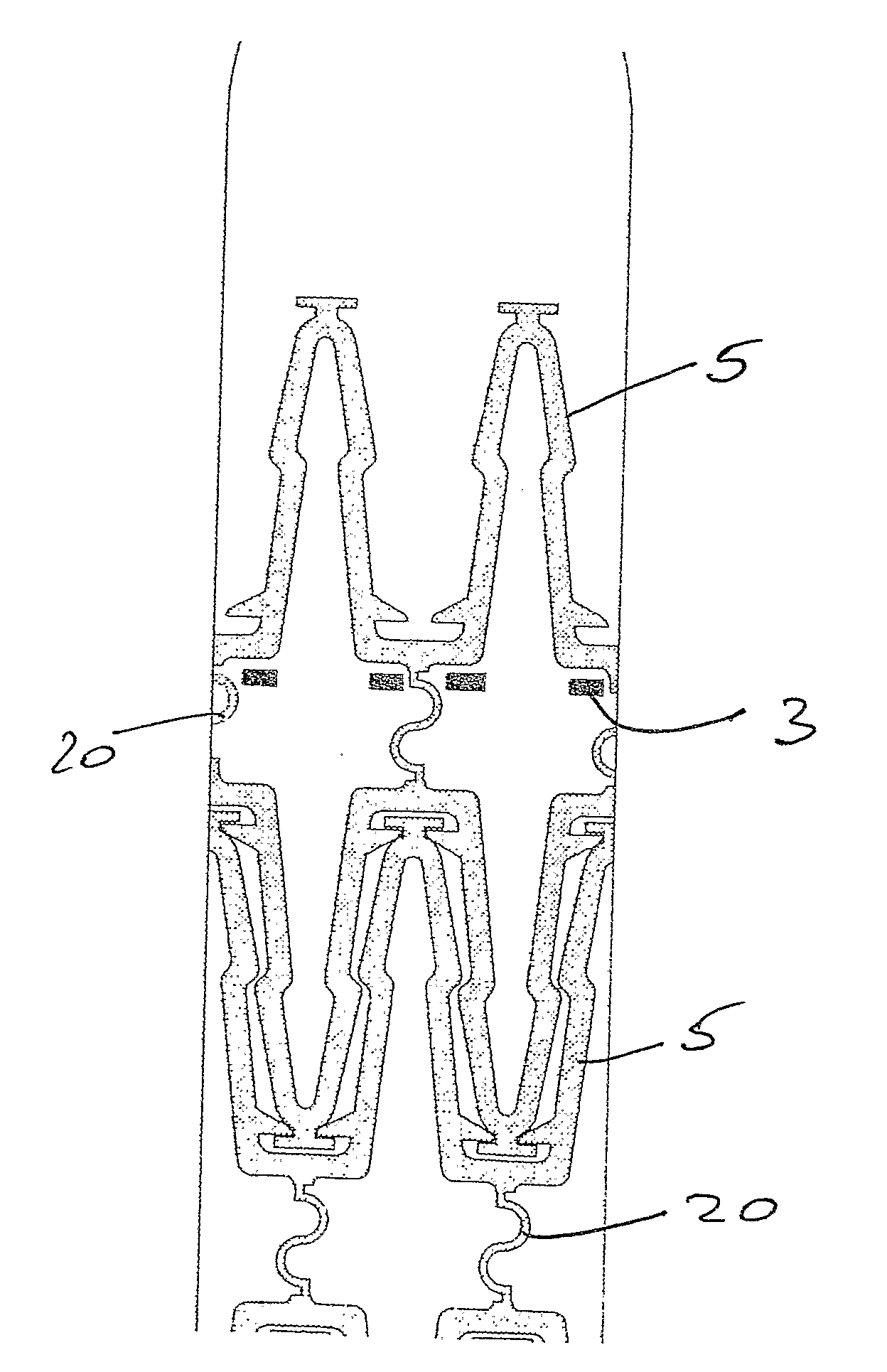
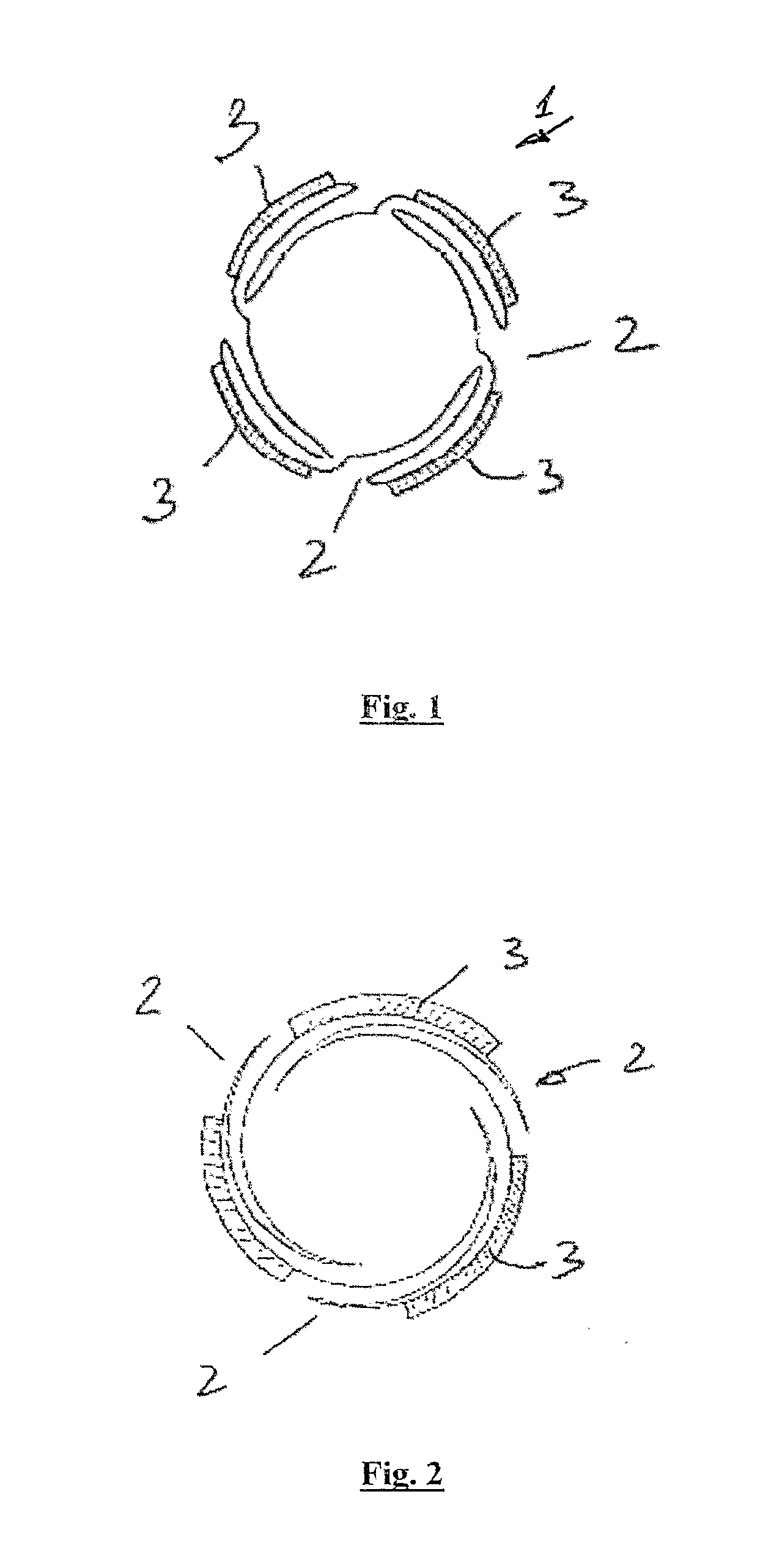
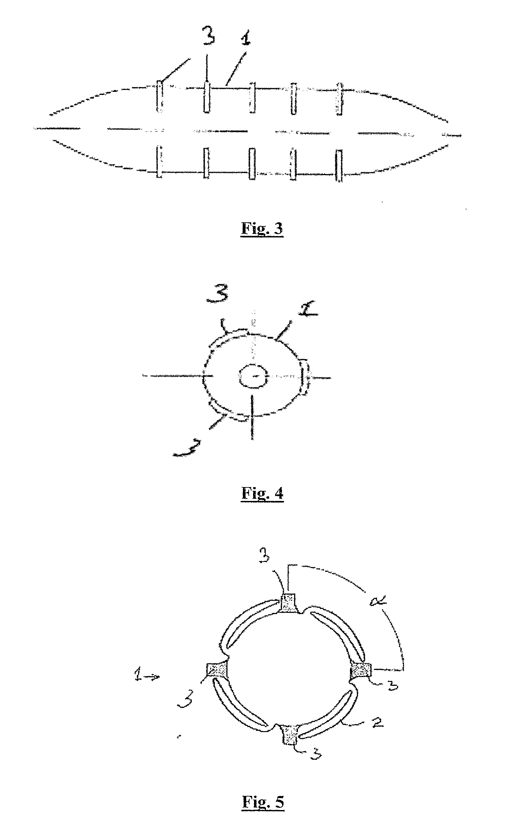
[0132]The invention provides a stent delivery balloon 1 to deploy a plurality of separate ‘mini-stents’5, which may or may not be interlocked / interlinked in the crimped configuration, into a bodily lumen at a controlled spacing. The balloon has formations for retaining the stents in a designed position, or for controlling the movement of the stents along their delivery balloon. The formations may comprise ridges 3, or retractable bridging elements, on the surface of the balloon 1 to control both the expansion of the multiple stents 5 from a single balloon 1 and also the coverage of the vessel wall following stenting.

[0133]In one case the ridges 3 are integral parts of the delivery balloon surface. They are designed and positioned in such a way as to engage with the mini-stents 5 and restrict their translation and rotation with respect to the balloon surface until the balloon 1 has been fully inflated. When the mini-stents 5 have been delivered to the correct locations on the vessel ...


PUM


Abstract

A stent delivery balloon (1) is used to deploy a plurality of mini-stents (5) into a bodily lumen at a controlled spacing. The balloon (1) has formations (3) for retaining the stents in a designed position. The formations may comprise ridges (3), or retractable bridging elements, on the surface of the balloon (1) to control both the expansion of the multiple stents (5) from a single balloon (1) and also the coverage of the vessel wall following stenting.

Description

INTRODUCTION[0001]Stenting has been used as a means to combat coronary artery disease since the 1980s and has proved to be a highly successful and low-cost alternative to coronary bypass. Many stents developed for the peripheral vessels were based on platforms designed for coronary applications and were not designed with the unique operating environment of peripheral arteries in mind. To this day, the success rate of peripheral stenting remains far below that of coronary stenting, with higher incidences of restenosis following treatment (Shouse et al. Endovascular Today, 2005; 4, 60-66; Matsi et al. 1995, Clin Radiol. 50(4):237-44; Mukherjee et al. 2001. Cleve Clin J Med. 68(8):723-33; Schillinger et al. 2006. N Engl J Med. 354(18):1879-88).[0002]Peripheral arteries are highly flexible vessels which undergo various bending, twisting and torsion modes in multiple planes. Simultaneously, the relatively large diameters of peripheral vessels requiring stenting will mean a thicker vessel...

Claims


Application Information

Patent Timeline
Patent Type & Authority Applications(United States)
IPC IPC(8): A61F2/84A61F2/82
CPCA61F2/958A61F2002/9583A61F2002/9505A61F2002/826
Inventor KELLY, DANIEL JOHNPERICEVIC, IAN OWENSKASIRI, GHAHI SAEID
Owner TRINITY COLLEGE DUBLIN
Why Eureka
Try Eureka