Wheel suspension for a vehicle

a technology for suspension and wheels, applied in the direction of cycle equipment, instruments, transportation and packaging, etc., to achieve the effect of preventing or reducing measurement errors, increasing the signal quality of acceleration, and improving the stability

Inactive Publication Date: 2011-06-23
ZF FRIEDRICHSHAFEN AG
View PDF11 Cites 16 Cited by
  • Summary
  • Abstract
  • Description
  • Claims
  • Application Information

AI Technical Summary

Benefits of technology

[0027]The signal quality of the acceleration is incr...

Problems solved by technology

Furthermore, measures taken to integrate the sensors in chassis components and prote...

Method used


Image

  • Wheel suspension for a vehicle
  • Wheel suspension for a vehicle
  • Wheel suspension for a vehicle

Examples


example

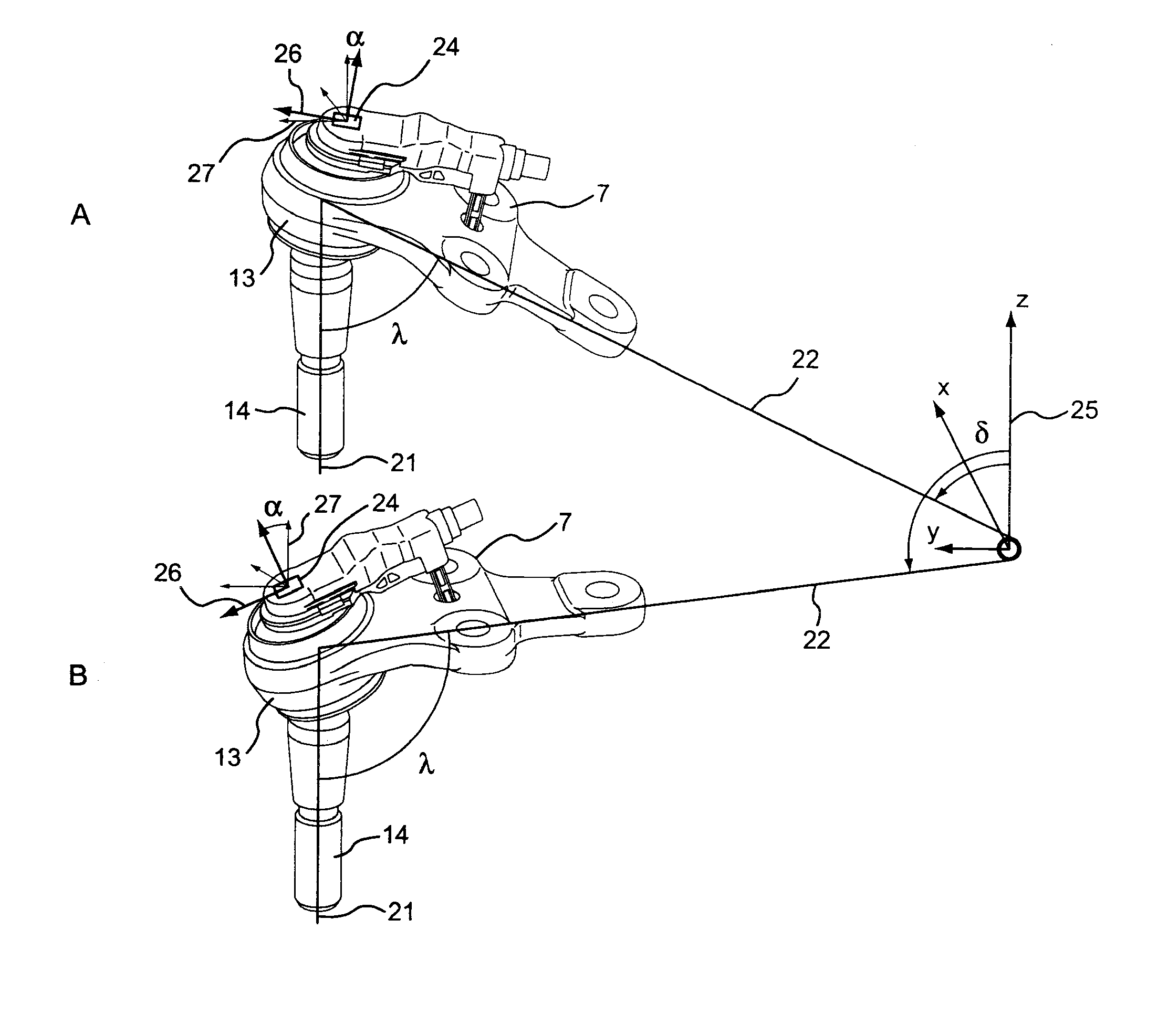
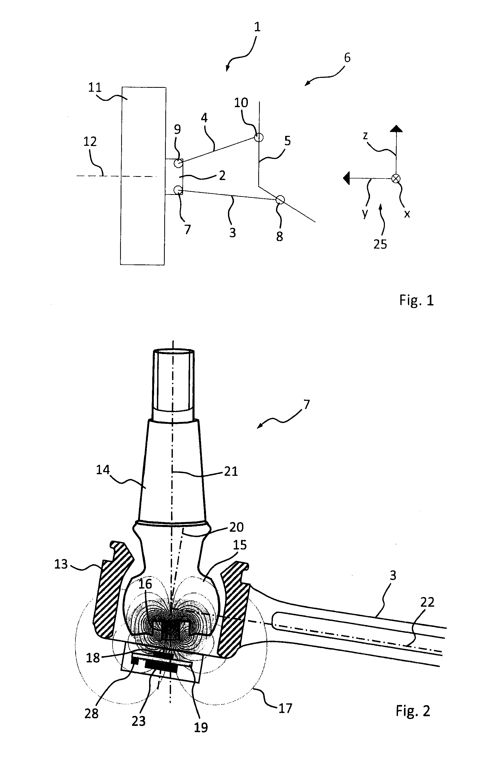
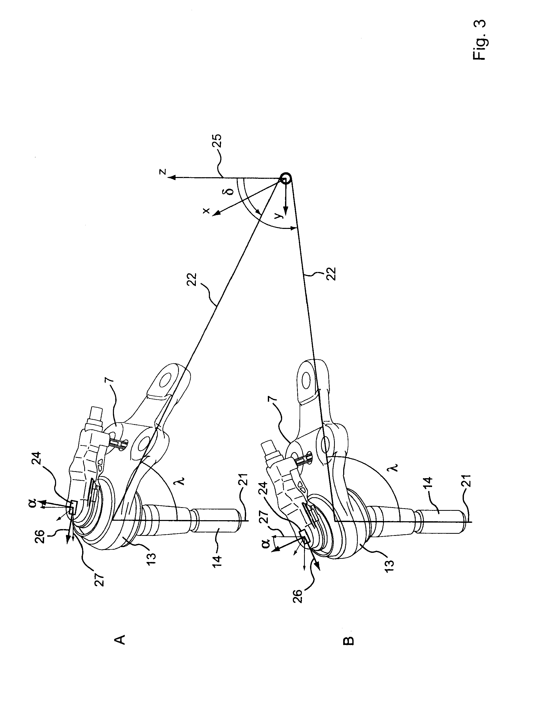
[0041]Compression motions cause the planar position of the acceleration sensor 23 to change continuously during vehicle operation relative to a stationary, horizontal orientation. These changes typically amount to ±10° and considerably more when very short connecting rods are used. Therefore, the vertical acceleration signal az is initially corrupted in a manner that is dependent on the compression travel and, of course, the inclination angle of the roadway. This error is moderate, however, because the following relationship applies:

azG-SENSOR—α=az·cos α=az for small angles α<10°

[0042]Given a planar angular deviation of 10°, a systematic measurement error of approximately 1.5% results. During vehicle operation, however, accelerations occur in the horizontal direction that are considerable and in some cases last for longer periods of time and, as a disturbance variable, have a sustained effect on the signal quality (direction) and quantity (amplitude) of the vertical acceleration tha...


PUM


Abstract

A wheel suspension for a vehicle comprising a wheel carrier (2), a vehicle wheel (11), which is rotatably supported on the wheel carrier (2), at least one coupling member (3), which pivotally connects the wheel carrier (2) to a body (5) of the vehicle (6), at least first and second joints (7, 8), one of which is installed between the coupling member (3) and the wheel carrier (2) and other of which is installed between the coupling member (3) and the body (5). At least one measuring device is integrated into a first joint (7) and comprises at least one angular sensor (16, 18) by which the deflection (λ) of the first joint (7) is, or can be, detected. The measuring device comprises at least one acceleration sensor (23).

Description

[0001]This application is a National Stage completion of PCT / DE2009 / 050035 filed Jul. 6, 2009, which claims priority from German patent application serial no. 10 2008 040 212.5 filed Jul. 7, 2008.FIELD OF THE INVENTION[0002]The invention relates to a wheel suspension for a vehicle, comprising a wheel carrier, a vehicle wheel which is rotatably mounted on the wheel carrier, at least one coupling member, by way of which the wheel carrier is pivotally connected to a body of the vehicle, at least two joints, one of which is installed between the coupling member and the wheel carrier, and another is installed between the coupling member and the body, and at least one measuring device which is integrated into a first of the joints and comprises at least one angular sensor, using which the deflection of the first joint is or can be detected. The invention furthermore relates to the use of an angular sensor and a method for correcting angular errors.BACKGROUND OF THE INVENTION[0003]An accel...

Claims


Application Information

Patent Timeline
IPC IPC(8): G06F19/00
CPCB60G7/005B60G2800/702B60G2200/144B60G2204/11B60G2204/116B60G2204/148B60G2204/41B60G2204/416B60G2206/11B60G2400/051B60G2400/10B60G2401/172B60G2401/904B60G2600/22B60G17/01908B60G7/00B60G17/019
Inventor KLANK, MICHAELGARTNER, ANDREAS
Owner ZF FRIEDRICHSHAFEN AG
Why Eureka
Try Eureka