
Circulation Element for Ball Screw

a technology of circulation elements and ball screws, which is applied in the direction of gearing elements, hoisting equipments, gearing components, etc., can solve the problems of increased manufacturing costs, inability to match the circulation passages of circulation elements, and longer process time, so as to reduce the operating noise of the ball screw and save manufacturing costs

Active Publication Date: 2011-06-30
HIWIN TECH
View PDF26 Cites 7 Cited by
  • Summary
  • Abstract
  • Description
  • Claims
  • Application Information

AI Technical Summary

Benefits of technology

[0007]The primary objective of the present invention is to open up and develop circulation elements used for a ball screw having a short lead (i.e. having a small lead angle) or more than two rolling trenches, and to save the manufacturing cost and decrease operating noise of the ball screw.

Problems solved by technology

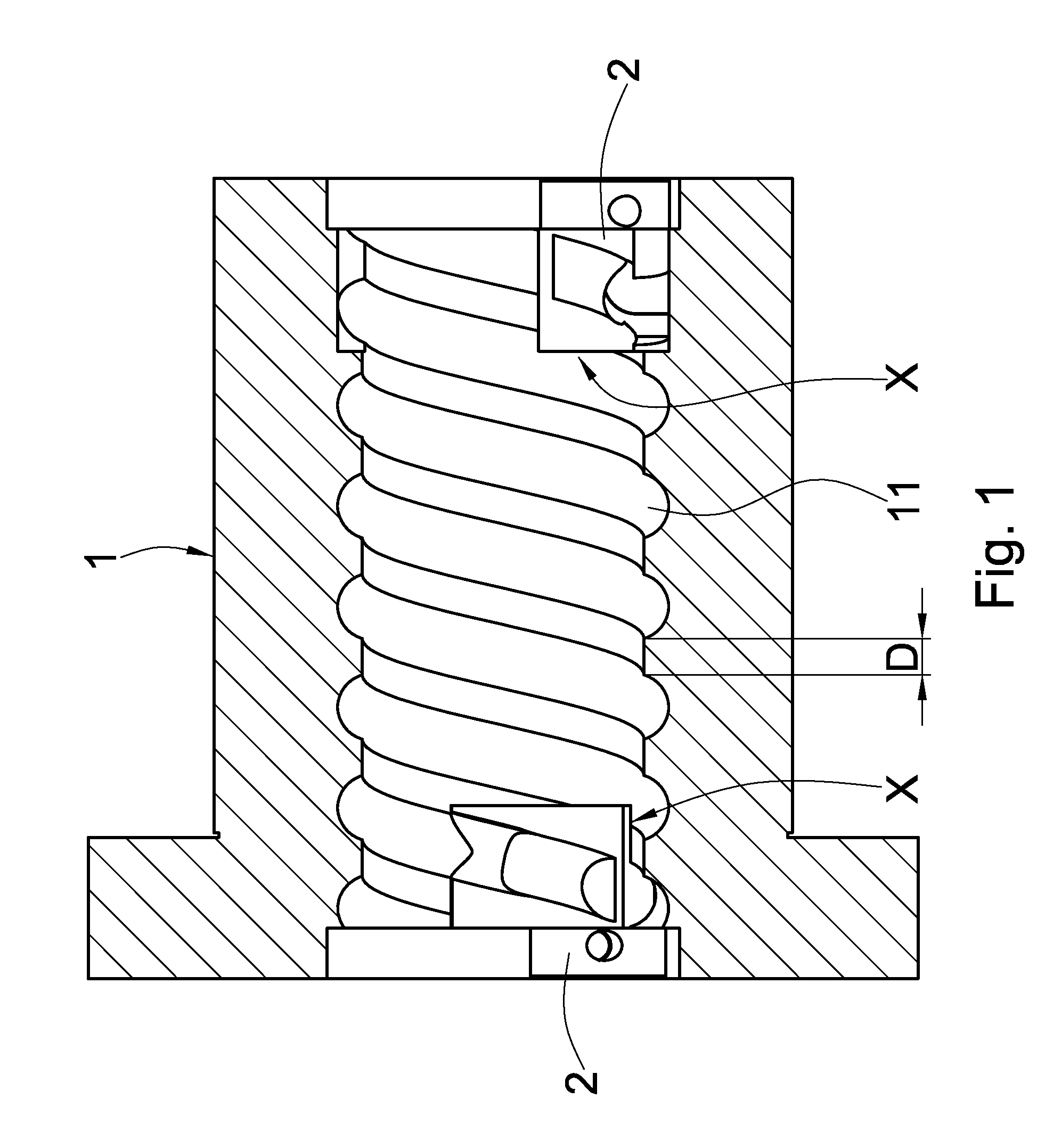
However, the circulation passages formed on the cap nut is curved and has a curved surface, and the processing would be difficult, the process time would be longer, and the manufacturing cost would be increased thereby.
Even if the process is completed, the circulation passages of the circulation elements may not be matched.
The technology disclosed in this Japan publication patent cannot solve the problems coming from the cap nut having a short lead (i.e. having a small lead angle) or more than two rolling trenches.

Method used


Image

  • Circulation Element for Ball Screw
  • Circulation Element for Ball Screw
  • Circulation Element for Ball Screw

Examples


Embodiment Construction

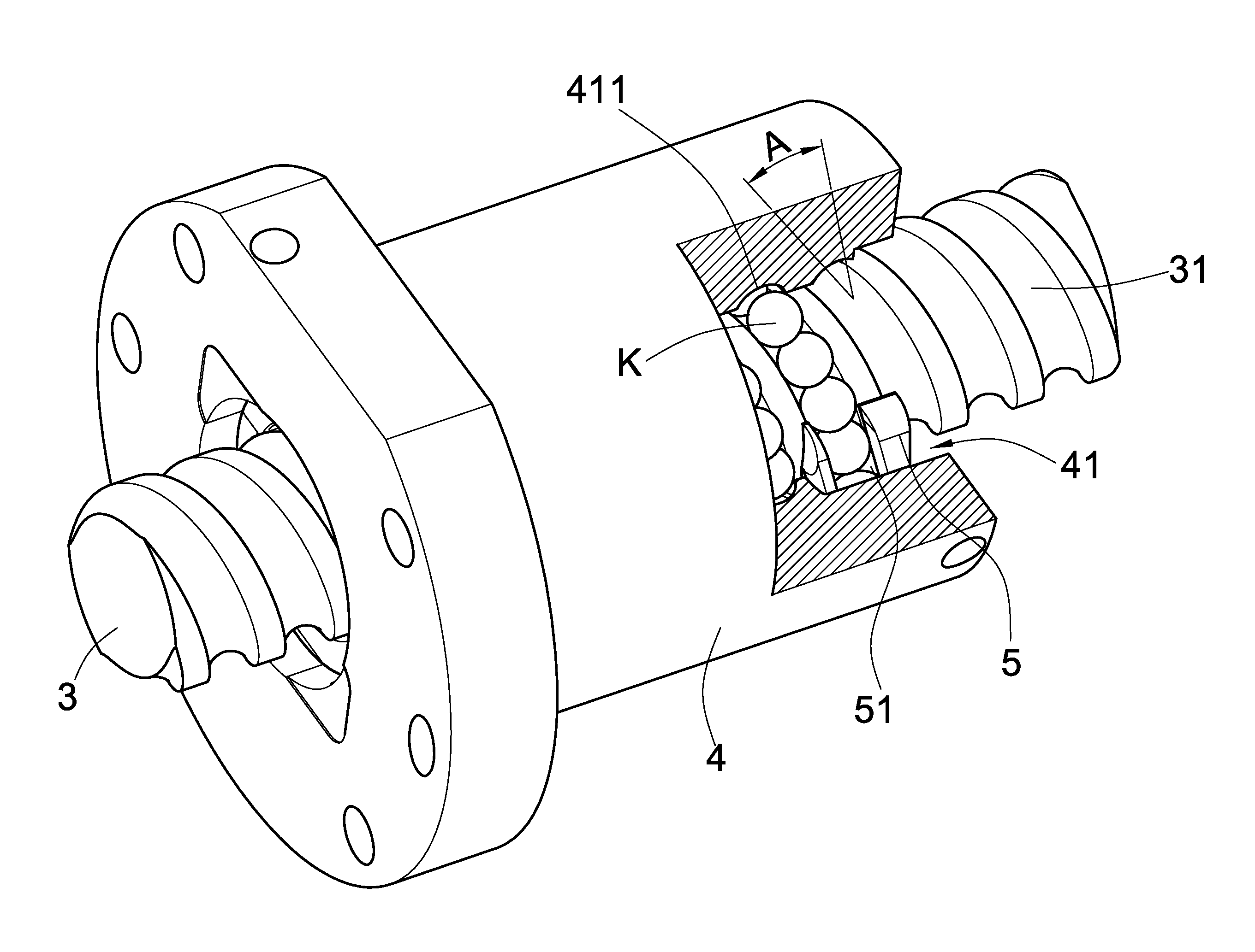
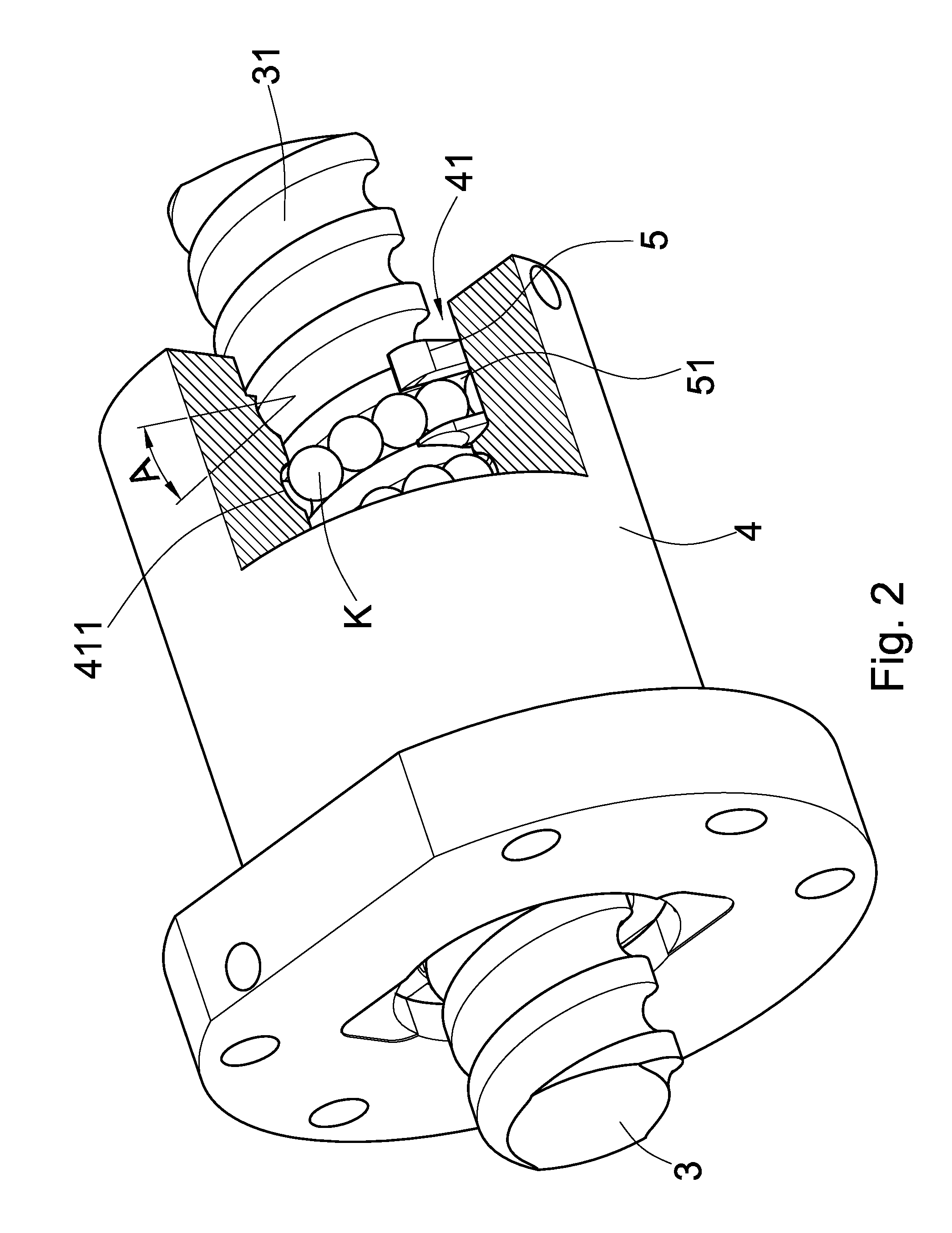
[0029]Referring to FIG. 2 to FIG. 7, the present invention is a ball screw having circulation elements, comprising:

[0030]a crew 3, being formed with a spiral rolling trough 31 at an outer edge thereof;

[0031]a cap nut 4, being formed with a through hole 41 for the screw 3 to insert through, an inner edge of the through hole 41 formed with a rolling trench 411 relative to the rolling trough 31, the rolling trench 411 and the rolling trough 31 forming a loading path, the loading path having a lead angle A, and the cap nut 4 having a circulation hole 42, being formed through two ends of the cap nut along an axial direction, and a mounting trough 43, being formed at two ends of the circulation hole 42 and connecting with the rolling trench 411;

[0032]two circulation elements 5, being formed at the mounting trough 43, each the circulation elements 5 being formed with a circulation passage 51, two ends of the circulation passage 51 connecting to the loading path and the circulation hole 42 ...


PUM


Abstract

This invention is revises the cap nut which the custom knows to suppose it to install trough's outline, will cause to install the dadoing to lead (lead angle to be small) lowly or on two above trundle ditch cap nut will not have the broken tooth's question, when will process should install the trough, only need use the face cutter then to process the forming, will reduce the production cost; And return circuit of this invention all establishes in the backflow part, therefore may promote and the cap nut supposes the backflow hole and the load way grade of fit, causes to roll the moving parts movement to be smoother, and reduces the noise production.

Description

BACKGROUND OF THE INVENTION[0001]1. Field of the Invention[0002]The present invention provides circulation elements for a linear transmission element. In particular, the present invention relates to an arrangement of circulation elements and cap nuts for ball screw.[0003]2. Descriptions of the Related Art[0004]FIG. 1 illustrates an arrangement of the circulation elements and the cap nut of the ball screw of the prior art. The circulation elements 2 are mounted on a cap nut 1 having a short lead (i.e. having a small lead angle) or more than two rolling trenches 11. With the two recited limitations, the thickness D between the rolling trenches 11 of the cap nut 1 would be thinner. A mounting trough should be formed on the cap nut 1 for mounting the circulation elements 2, and the outline of the mounting trough should match the outline of the circulation elements 2. The general outline of the circulation elements 2 is a rectangle as shown in figure. The mounting trough, having the same...

Claims


Application Information

Patent Timeline
IPC IPC(8): F16H25/22
CPCY10T74/19772Y10T74/19749Y10T74/19767F16H25/2219
Inventor LEE, YU-SHAN
Owner HIWIN TECH
Learn More