
Infrared sensor and infrared sensor module

a technology of infrared sensor and infrared sensor, which is applied in the direction of optical radiation measurement, instruments, material analysis, etc., can solve the problems of complex work of mounting the sensing units in the vacuum sealed case, noise in the infrared sensor, and the output signal is prone to be noisy, so as to reduce the number of manufacturing process steps of the module, increase the detection precision, and reduce the effect of pressur

Inactive Publication Date: 2011-06-30
ORMON CORP
View PDF4 Cites 16 Cited by
  • Summary
  • Abstract
  • Description
  • Claims
  • Application Information

AI Technical Summary

Benefits of technology

[0010]An object of the present invention is to provide an infrared sensor and an infrared sensor module having reduced noise, improved detection precision, and reduced manufacture cost.

Problems solved by technology

However, a conventional infrared sensor has a configuration such that the arithmetic circuit is mounted in a position apart from the sensing unit, and noise tends to occur in the output signal from the sensing unit.
By connecting the plurality of sensing units to one arithmetic circuit, the sampling frequency be comes high, and it causes noise.
However, in an infrared sensor so configured, heat (infrared light) generated by the arithmetic circuit may cause noise in the infrared sensor.
Moreover, a work of mounting the sensing units in the vacuum-sealed case includes a complicated work such as degasifying work, and expensive parts, special adhesive, and the like are necessary for the case requested to have high air tightness.
Therefore, the conventional configuration in which the sensing units are housed in the vacuum-sealed case has a problem also from the viewpoint of manufacture cost.

Method used


Image

  • Infrared sensor and infrared sensor module
  • Infrared sensor and infrared sensor module
  • Infrared sensor and infrared sensor module

Examples


embodiment

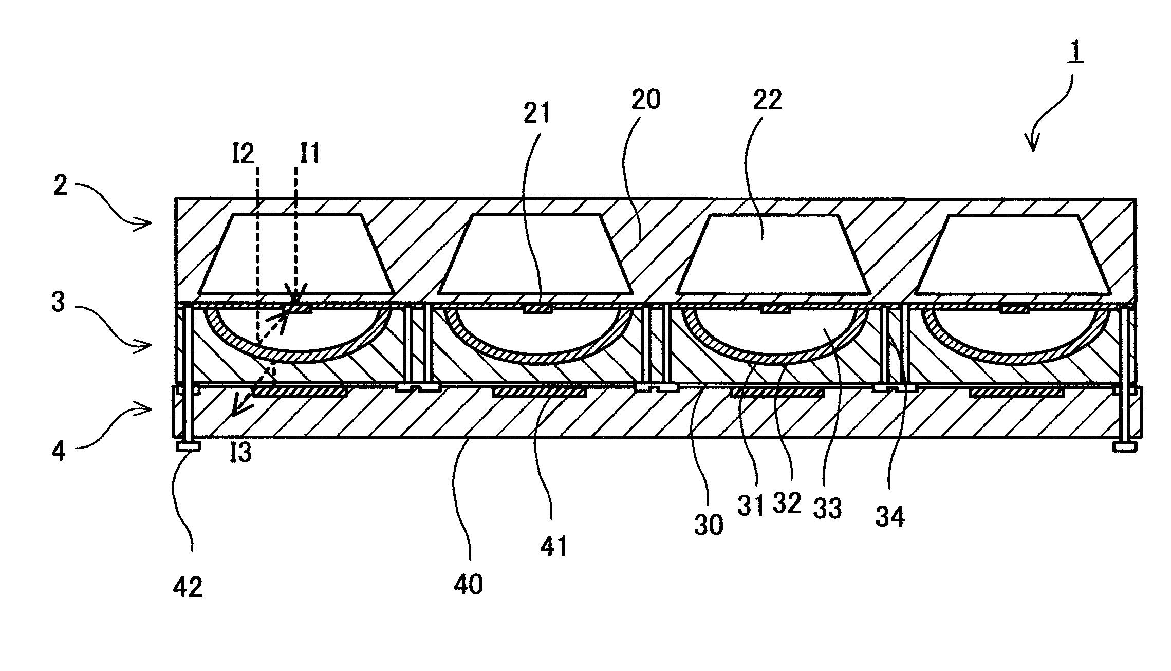
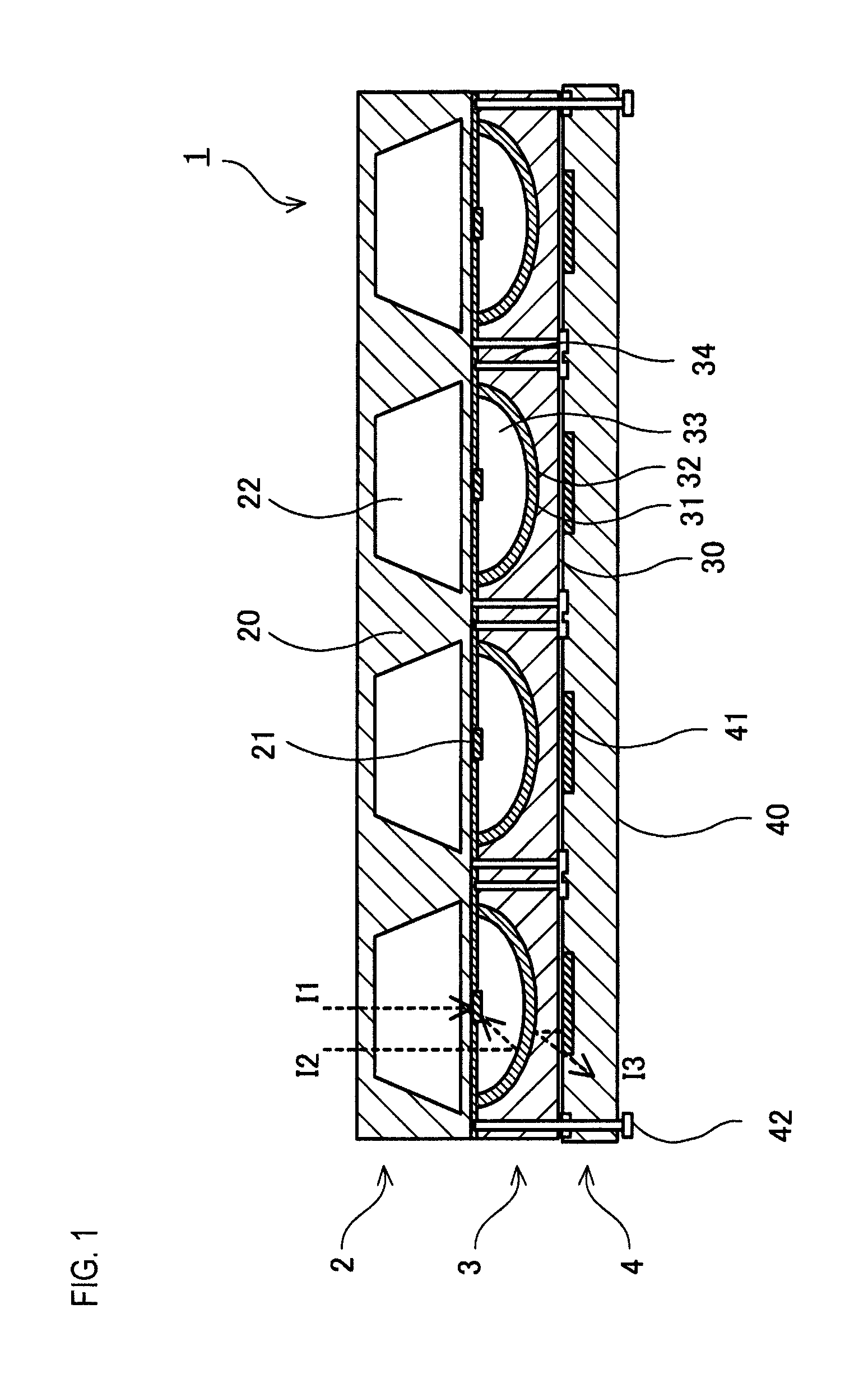
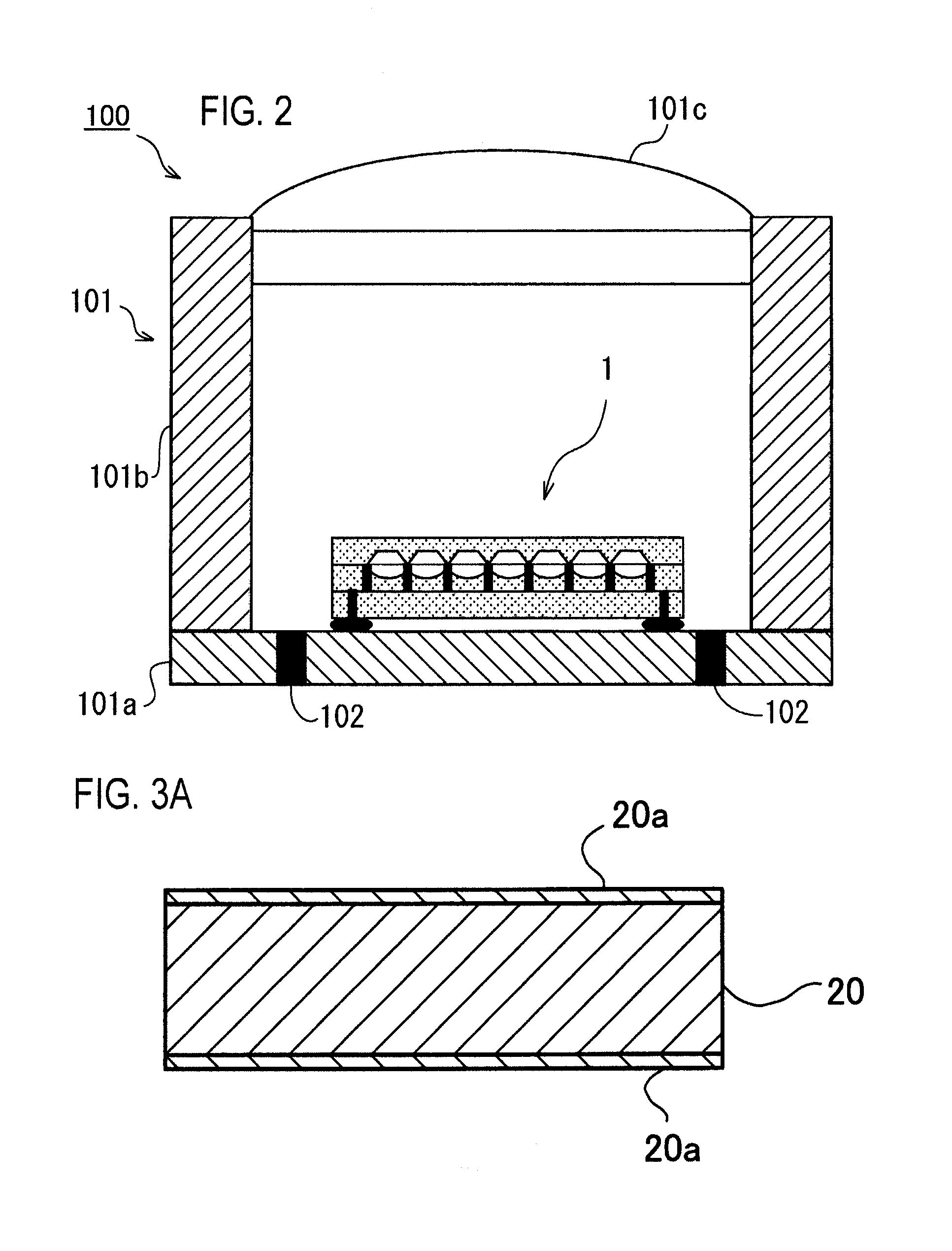
[0062]With reference to FIGS. 1 to 7, an infrared sensor and an infrared sensor module according to an embodiment will be described. FIG. 1 is a schematic cross-sectional view of the infrared sensor according to an embodiment of the invention. FIG. 2 is a schematic cross-sectional view of the infrared sensor module according to an embodiment of the invention. FIGS. 3A to 3L are schematic views for explaining a method for manufacturing an infrared sensing device. FIGS. 4A to 4F are schematic views for explaining a method for manufacturing a reflection layer. FIGS. 5A to 5C are circuit configuration diagrams of the infrared sensor according to an embodiment. FIGS. 6A and 6B are schematic cross-sectional views of the infrared sensor according to an embodiment of the invention. FIGS. 7A to 7C are schematic cross-sectional views of the infrared sensor according to an embodiment of the invention.

[0063]As shown in FIG. 1, an infrared sensor 1 according to an embodiment of the invention has...


PUM


Abstract

The present invention provides an infrared sensor and an infrared sensor module having reduced noise, improved detection precision, and reduced manufacture cost. The infrared sensor includes a first substrate transmitting infrared light including at least one reduced-pressure and sealed cavity, at least one infrared sensing unit provided on the side of the first substrate, and at least one infrared sensing unit generating an output change. The infrared sensor includes a second substrate stacked on the first substrate with a recess, a reflection face capable of reflecting the infrared light, and at least one arithmetic circuit for amplifying or integrating an output, arranged in such a manner that the reflection face is sandwiched between the at least one sensing unit and the least one arithmetic circuit.

Description

BACKGROUND OF THE INVENTION[0001]1. Field of the Invention[0002]The present invention relates to an infrared sensor and an infrared sensor module.[0003]2. Description of the Related Art[0004]Hitherto, an infrared sensor using, as a sensing unit, an element (thermopile) that generates voltage when heat is applied is known (refer to Japanese Patent Application Laid-Open Nos. H06-229821, H11-258038, H11-258040, H11-258041, 2000-65639, 2000-221080, and 2000-292254). The thermopile receives infrared light emitted from an object and, when a temperature difference occurs, generates a voltage difference corresponding to the temperature difference due to the so-called Seebeck effect. By detecting the voltage difference as a function of the temperature change, the temperature of an object can be sensed.[0005]Such an infrared sensor is used as a sensor module in which a plurality of sensing units is arranged in the vertical and horizontal directions (in an array) in a vacuum-sealed case in ord...

Claims


Application Information

Patent Timeline
Patent Type & Authority Applications(United States)
IPC IPC(8): G01J5/20
CPCG01J5/02G01J5/0215G01J5/024G01J5/04G01J5/045H01L27/14649G01J5/0815G01J5/0853H01L27/14618H01L27/14625G01J5/08H01L2924/0002H01L2924/00
Inventor OHHIRA, MAKOTOAITA, FUMIJIKOYAMA, YUTAKASASAKI, SHO
Owner ORMON CORP
Learn More