Sheet conveying apparatus and image forming apparatus

a conveying apparatus and a technology of forming apparatus, applied in the direction of registering devices, thin material processing, article separation, etc., can solve the problems of unstable rotation difficulty in smoothly altering the rotation direction etc., to achieve the effect of reducing the rotational member of the conveying ball and effective pressing

Inactive Publication Date: 2011-06-30
CANON KK
View PDF14 Cites 11 Cited by
  • Summary
  • Abstract
  • Description
  • Claims
  • Application Information

AI Technical Summary

Benefits of technology

[0009]According to the present invention, since the conveying rotation member is supported by the two driving rollers and the driven roller from below so that the conveying rotation member is effectively pressed with the driving rollers, and fluctuations in a frictional force between the two driving rollers, as well as the driven roller, and the conveying rotation member can be reduced. Therefore, since the rotating speed and rotation direction of the conveying rotation member are stabilized, the sheet can be conveyed stably at a desired conveying speed and a desired direction.

Problems solved by technology

In the case when the frictional force between the conveying ball and the ball supporting member is changed in this manner, the rotation of the conveying ball becomes unstable.
Moreover, when the pressing force of the rotation rolls is large, the frictional force between the conveying ball and the ball supporting member becomes excessively large to sometimes cause a difficulty in smoothly altering the rotation direction of the conveying ball.

Method used


Image

  • Sheet conveying apparatus and image forming apparatus
  • Sheet conveying apparatus and image forming apparatus
  • Sheet conveying apparatus and image forming apparatus

Examples


Embodiment Construction

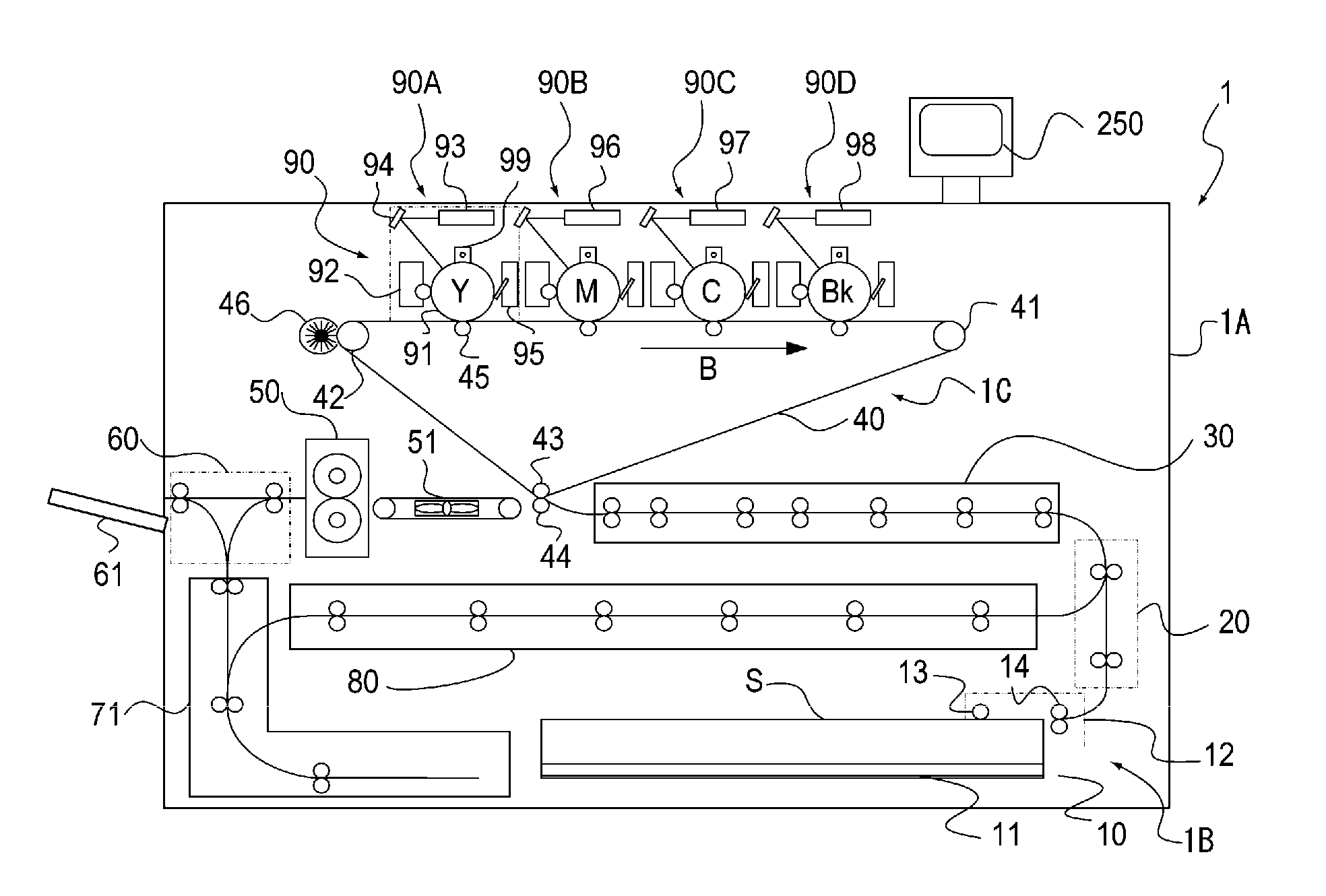
[0025]FIG. 1 is a view that illustrates a schematic structure of a color image forming apparatus of one example of the image forming apparatus according to an embodiment of the present invention. In FIG. 1, reference numeral 1 represents an image forming apparatus and 1A represents an image forming apparatus main body (hereinafter, referred to as an apparatus main body). The apparatus main body 1A is provided with an image forming section 90 that forms an image on a sheet S, and a sheet supplying device 1B that supplies the sheet S. Moreover, the apparatus main body 1A is provided with a registration portion 30 that serves as a sheet conveying device for conveying the sheet S supplied from the sheet supplying device 1B to an image forming section 90 disposed on the downstream side in a sheet conveying direction. Furthermore, on the upper surface of the apparatus main body 1A, an operation portion 250, which allows the user to carry out various inputting operations / setting operations...


PUM


Abstract

The apparatus of the present invention is provided with: a spherical conveying rotation member that is driven to rotate in a desired direction; a driven rotation member disposed above the conveying rotation member so as to be pressed onto an upper portion of the conveying rotation member so that the driven rotation member nips a sheet in cooperation with the conveying rotation member to convey the sheet; two driving rollers press with the conveying rotation member so as to drive the conveying rotation member to rotate; and a driven roller that is made in press-contact with the conveying rotation member to be driven together therewith, and in this structure, the two driving rollers and the driven roller are disposed below the conveying rotation member so as to support the conveying rotation member by the two driving rollers and the driven roller from below.

Description

BACKGROUND OF THE INVENTION[0001]1. Field of the Invention[0002]The present invention relates to a sheet conveying apparatus provided with a spherical conveying rotation member and a driven rotation member pressed with the conveying rotation member so that a sheet is nipped to be conveyed by these members, and an image forming apparatus provided with such a sheet conveying apparatus.[0003]2. Description of the Related Art[0004]In general, image forming apparatuses, such as those of an electrophotographic system, an offset printing system, and an inkjet system, have been known. In recent years, in these image forming apparatuses, there have been increasing demands for a technique, upon conveying a sheet, the posture of the sheet is corrected with high precision. Normally, by correcting a skew feeding of a sheet and a positional deviation in the width direction thereof, the posture of the sheet is corrected so that positions of the sheet and an image to be formed are adjusted. Moreove...

Claims


Application Information

Patent Timeline
Patent Type & Authority Applications(United States)
IPC IPC(8): B65H5/06
CPCB65H5/062B65H7/10B65H9/16B65H2404/611B65H2511/24B65H2701/1315B65H2511/514B65H2513/108B65H2513/11B65H2513/41B65H2511/242B65H2220/02B65H2220/01B65H2220/03B65H2220/11B65H2513/10
Inventor FUJITA, TAKASHI
Owner CANON KK
Why Eureka
Try Eureka