Axial gap rotating electrical machine and rotor used therefor

a technology of axial gap and rotor, which is applied in the direction of dynamo-electric machines, magnetic circuit rotating parts, and shape/form/construction of magnetic circuits, etc. it can solve the problems of limiting the degree of freedom in changing the shape of magnets, increasing the cost of manufacturing, and eddy current loss, so as to reduce eddy current loss, reduce the cost of rotor, and simplify the manufacturing process

Active Publication Date: 2011-06-30
HITACHI METALS LTD
View PDF16 Cites 21 Cited by
  • Summary
  • Abstract
  • Description
  • Claims
  • Application Information

AI Technical Summary

Benefits of technology

[0013]According to the rotor structure of the axial gap rotating electrical machine of the present invention, it is possible to reduce eddy current loss in the rotor of the axial gap rotating electrical machine, simplify the manufacturing process, and provide a low-cost rotor.

Problems solved by technology

However, provided that the electromagnetic steel sheets are laminated in a radial direction of the rotor, a centrifugal force of the rotor becomes great.
Further, since a laminated core comprised of stamped electromagnetic steel sheets has a large residual stress, it needs to use a retention means other than an adhesive.
As a result, increasing the number of manufacturing process steps, raising the cost of manufacturing, and limiting the degree of freedom in changing the shapes of the magnets.
It should also be noted that the use of the reinforcements is likely to make an assembly process complex and increase the cost.

Method used


Image

  • Axial gap rotating electrical machine and rotor used therefor
  • Axial gap rotating electrical machine and rotor used therefor
  • Axial gap rotating electrical machine and rotor used therefor

Examples


first embodiment

[0030]A first embodiment of the present invention will now be described with reference to FIGS. 1 to 7.

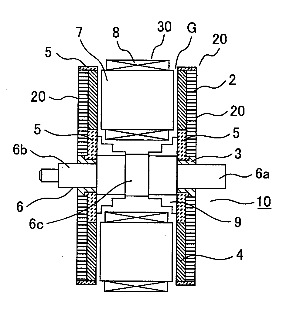
[0031]FIG. 1 shows an example of an axial gap motor according to the first embodiment of the present invention. In FIG. 1, a rotor and a stator are shown with a motor housing removed (not shown).

[0032]The axial gap motor 10 is configured so that a rotor 20 and a stator 30 are opposed to each other in an axial direction of a rotor shaft 6 with a gap G. The present embodiment examples the axial gap motor including two rotors and one stator in order to provide enhanced motor efficiency but it doesn't limit such a type thereof.

[0033]Referring to FIG. 1, each of electromagnets, which constitute the stator 30, is formed by a coil-mounted stator core which is obtained by mounting an electromagnetic coil 8 on each stator core 7. The electromagnetic coil 8 is wound around the stator core 7 in such a manner that its center is positioned in parallel with the axis of the rotor shaft 6. Plural ...

second embodiment

[0048]A second embodiment of the present invention will now be described. FIGS. 8 to 11 illustrate a rotor structure of an axial gap motor according to the second embodiment.

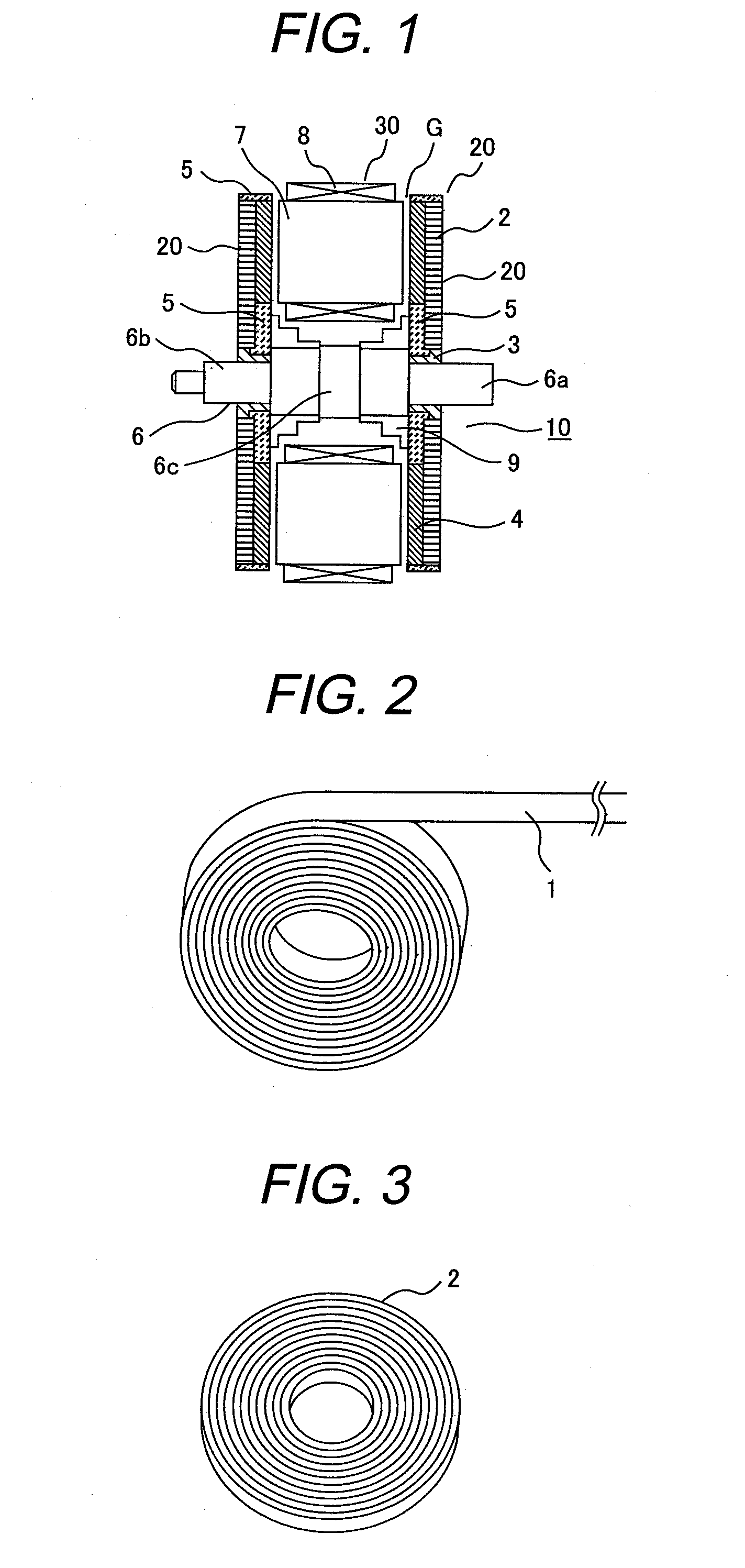
[0049]The rotor according to the present embodiment also uses an amorphous ribbon wound toroidal core as the rotor yoke 2, as is the case with the first embodiment. The rotor according to the present embodiment differs from the rotor according to the first embodiment in that the amorphous ribbon wound toroidal core 2 is formed by winding the amorphous magnetic metal ribbon 1 directly onto a rotor shaft 6′, as shown in FIG. 9, without using a rotor shaft use boss. In other words, the rotor yoke 2 formed by the amorphous ribbon wound toroidal core is directly mounted on the rotor shaft 6′.

[0050]FIG. 8 shows the rotor shaft 6′ used in the present embodiment. Portions 6a′, 6b′, 6c′ of the rotor shaft 6′ respectively correspond to the portions 6a, 6b, 6c shown in FIG. 1. The portion 6c′ of the rotor shaft 6′ is a por...

third embodiment

[0056]A third embodiment of the present invention will now be described. FIGS. 12 to 14 illustrate a rotor structure of an axial gap motor according to the third embodiment.

[0057]The axial gap motor according to the present embodiment includes one rotor and two stators.

[0058]FIG. 12 shows the amorphous ribbon wound toroidal core 2 as the rotor yoke is formed by directly winding an amorphous magnetic metal ribbon onto a shaft 6, in the same manner as indicated in FIG. 9, at the rotor yoke position of an axial central portion 6d″ (see FIG. 14) of a rotor shaft 6″. Portions 6a″ and 6b″ of the rotor shaft 6″ correspond to portions 6a and 6b in the first embodiment and are supported by the motor housing via a radial bearing (not shown). The present embodiment is similar to the foregoing embodiments in that the amorphous ribbon wound toroidal core 2 is impregnated with resin 5.

[0059]In the present embodiment, the same magnets 4 as in the first and second embodiments are bonded to both sur...


PUM


Abstract

In the axial gap rotating electrical machine, the rotor includes a rotor yoke that is formed by wrapping amorphous ribbon wound toroidal core, which is obtained by winding an amorphous magnetic metal ribbon into a toroidal core. Magnets having plural poles are circumferentially disposed on a stator-facing surface of the amorphous ribbon wound toroidal core.

Description

CLAIM OF PRIORITY[0001]The present application claims priority from Japanese patent application serial no. 2009-298070, filed on Dec. 28, 2009, the content of which is hereby incorporated by reference into this application.FIELD OF THE INVENTION[0002]The present invention relates to an axial gap rotating electrical machine in which a stator and a rotor are opposed to each other in an axial direction of a rotary shaft with a gap therebetween. The present invention also relates to the rotor.BACKGROUND OF THE INVENTION[0003]As regards rotating electrical machines such as an axial gap motor, there are known various structures and related technologies.[0004]For example, in a rotor structure for an axial gap motor, which is disclosed in JP2006-166634A, mutually opposite polarity permanent magnets as rotor magnetic poles are alternately disposed in a circumferential direction of a rotor core made of a magnetic material; and the circumferential length of each permanent magnet varies along a...

Claims


Application Information

Patent Timeline
Patent Type & Authority Applications(United States)
IPC IPC(8): H02K1/27H02K16/02
CPCH02K21/24H02K1/2793H02K1/2795
Inventor WANG, ZHUONANENOMOTO, YUJIMASAKI, RYOSOITABASHI, HIROMITSUYOSHIKAWA, TOMIO
Owner HITACHI METALS LTD
Why Eureka
Try Eureka