Power system

a power system and power technology, applied in the field of power systems, can solve the problems of inability to preliminarily detect problems before power charge and prevent problems from happening, and achieve the effect of preventing the carrying out of inappropriate power charges

Inactive Publication Date: 2011-06-30
HONDA MOTOR CO LTD
View PDF6 Cites 19 Cited by
  • Summary
  • Abstract
  • Description
  • Claims
  • Application Information

AI Technical Summary

Benefits of technology

[0018]According to the power system of the fifth aspect of the present invention, the charge state of the power storing member charged by the external power, such as the connection state between the external power connecting member and the power supplying connector prior to the power charge, the charge state (progressing state of the power charge) of the power storing member by the external power in the power charge, or the completed charge state (energization is stopped) posterior to the power charge, is displayed by the display member. According thereto, either prior to or posterior to the power charge, whether or not appropriate power charge or an operation for the power charge is being carried out can be reported to a user; thereby, an appropriate connection to the external power can be assisted and inappropriate power charge can be prevented from being carried out.

Problems solved by technology

However, even though it is possible for the conventional power charge system to monitor and report the charge state after the power charge is initiated, it is impossible for it to preliminarily detect problems happened prior to the power charge and to take measures to prevent the problems from happening.
Especially in present days when the power storing member and the power charge device are of various specifications, the power charge will not be carried out if the power storing member and the power charge device are not matched in specifications or a connector and a plug are not consistent; moreover, problems will happen during the power charge if the power charge is carried out in an inappropriate manner.

Method used


Image

  • Power system
  • Power system
  • Power system

Examples


Embodiment Construction

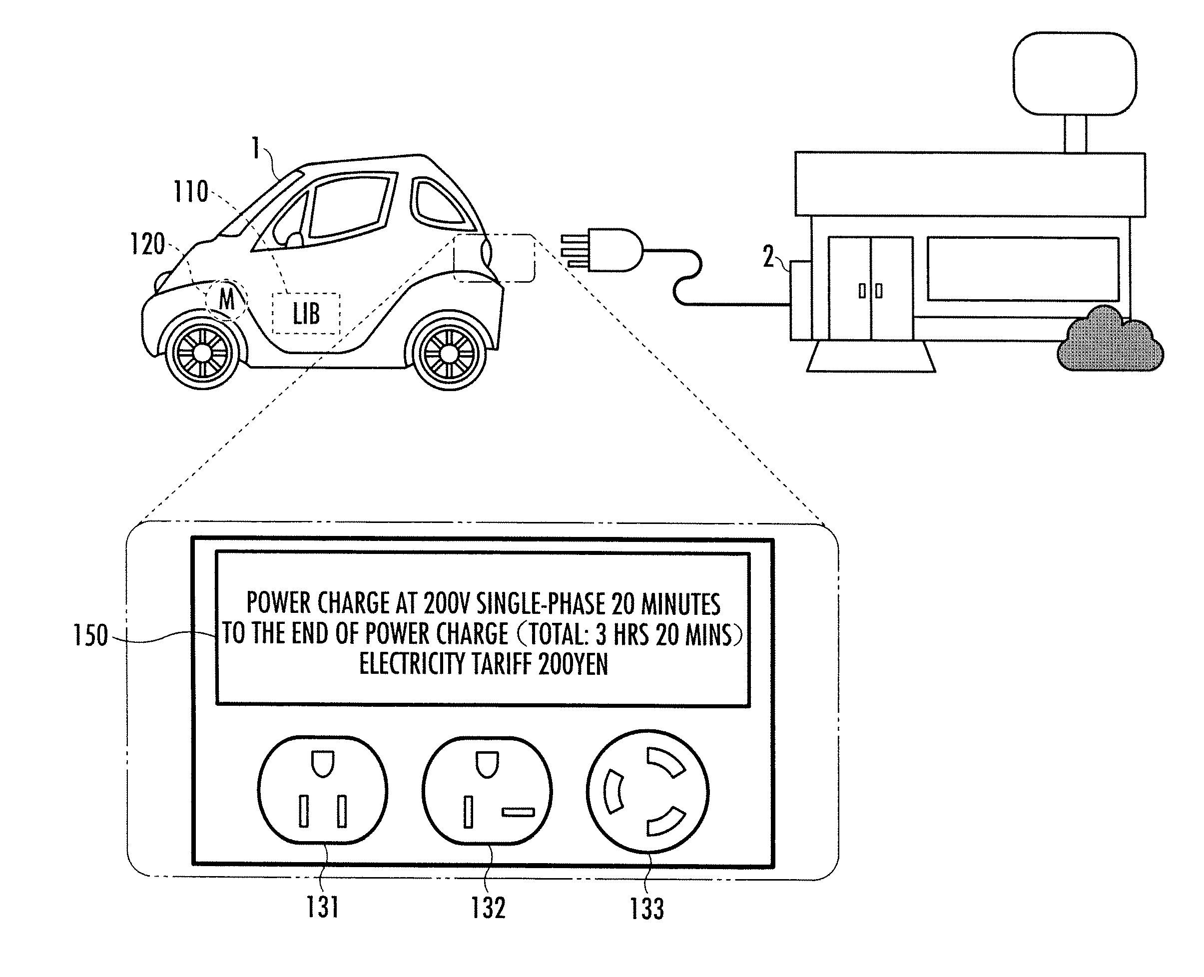
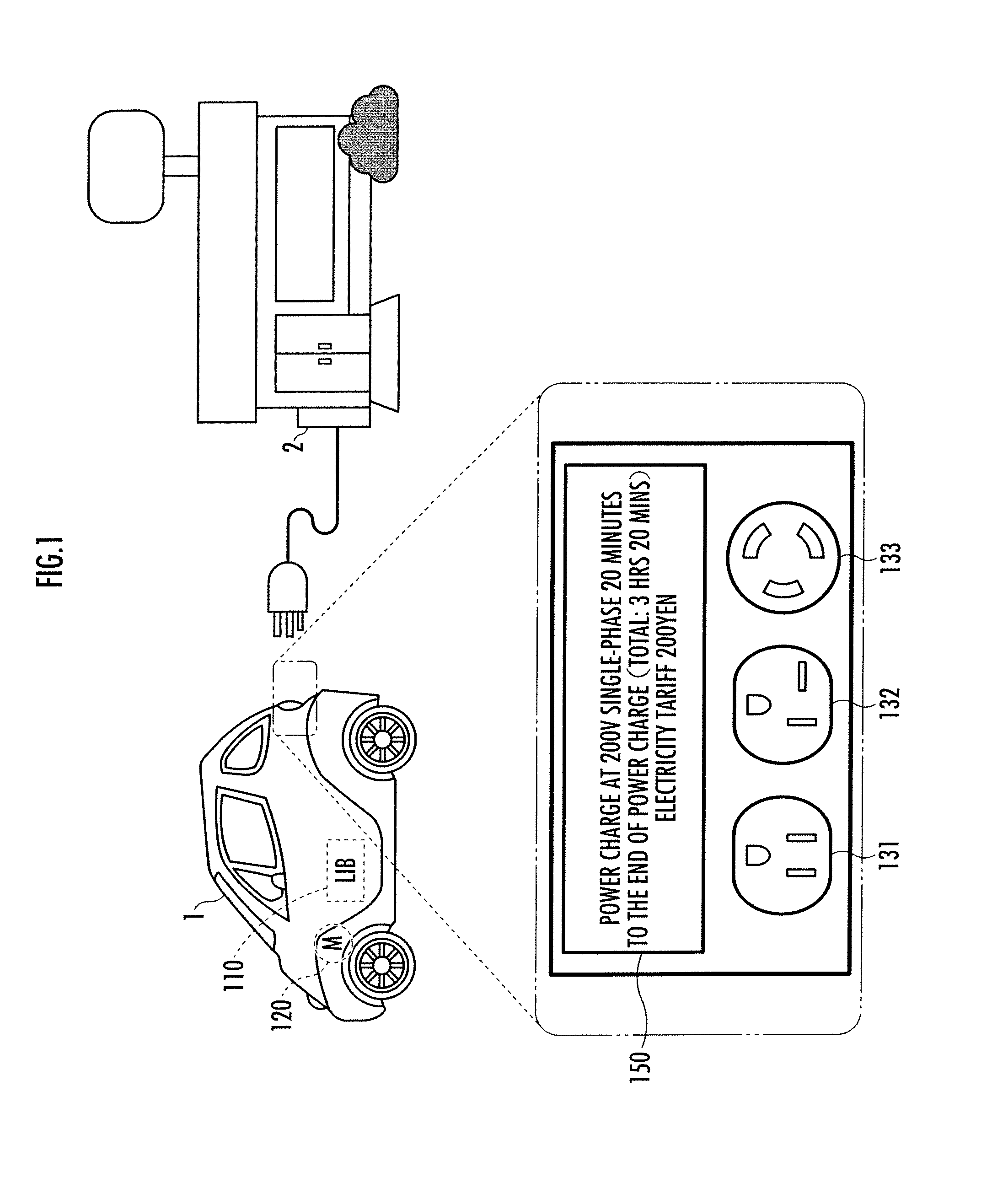
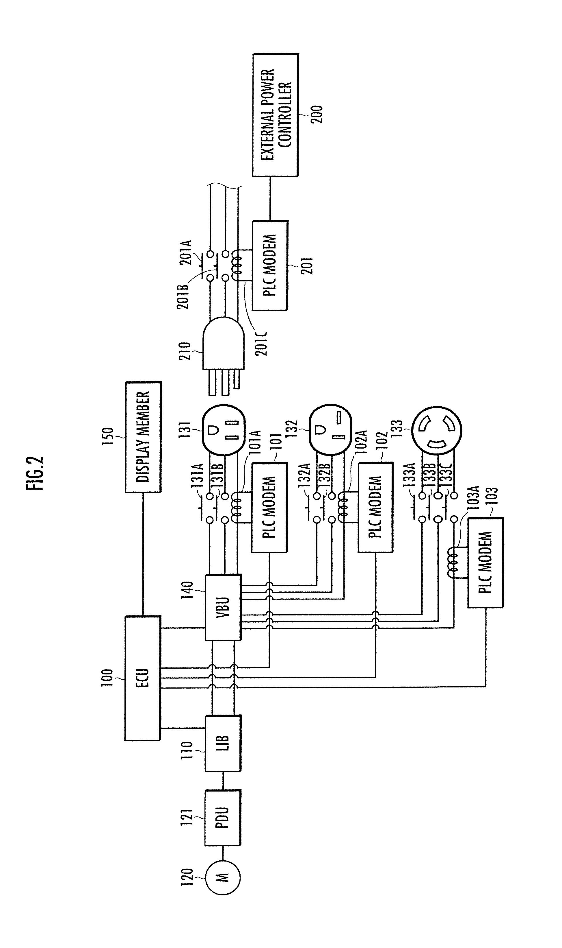
[0023]As illustrated in FIG. 1 and FIG. 2, a power system according to an embodiment of the present invention is mounted in a vehicle 1 and is provided with an electronic control unit 100, a secondary battery 110 serving as a power storing member, an electric motor 120, plural types of external power connecting members 131, 132 and 133, and a display member 150. The power system of the present invention charges the secondary battery 110 from a power charge station 2 serving as an external power disposed in a convenience store, a shopping center or the like via the external power connecting members 131, 132 and 133. The details of the electronic control unit 100 will be described hereinafter.

[0024]The secondary batter 110 may be, for example, a lithium ion battery with an output voltage varying in a range from about 300V to 500V. The secondary battery 110 is connected to the electric motor 120 via a PDU (Power Drive Unit) 121.

[0025]Further, the secondary battery 110 is connected to t...


PUM


Abstract

Provided is a power system capable of assisting an appropriate connection to an external power and preventing inappropriate power charge from being carried out. The power system mounted in a vehicle (1) is provided with a secondary battery (110), an electric motor (120) connected to the secondary battery (110) for driving the vehicle (1), a plurality of external power connecting members (131, 132 and 133) connected respectively by plural types of power supplying connectors for supplying electric power from an external power to the secondary battery (110), and movable insulation plates (171, 172 and 173) configured to block a further connection of a power supplying connector to the other external power connecting members when either one of the external power connecting members (131, 132 and 133) is detected by the connection detecting member to have a connection to a corresponding power supplying connector.

Description

BACKGROUND OF THE INVENTION[0001]1. Field of the Invention[0002]The present invention relates to a power system mounted in a vehicle.[0003]2. Description of the Related Art[0004]Conventionally, there has been known a power charge system disposed in a vehicle mounted with a power storing member for charging an external device with the power storing member in Japanese Patent Laid-open No. H9-233720. In the power charge system, the charge state of the power storing member is monitored by a controller mounted in the vehicle. When an abnormality such as a connector has been pulled out or the like happens, it is reported to a power charge device outside the vehicle (Paragraph 0011 of Japanese Patent Laid-open No. H9-233720).[0005]However, even though it is possible for the conventional power charge system to monitor and report the charge state after the power charge is initiated, it is impossible for it to preliminarily detect problems happened prior to the power charge and to take measur...

Claims


Application Information

Patent Timeline
Patent Type & Authority Applications(United States)
IPC IPC(8): H02J7/02B60L3/00H02J7/00
CPCB60L11/1818Y02T90/14Y02T10/7005B60L53/16Y02T10/70Y02T10/7072
Inventor NOGUCHI, MINORUHIRAKAWA, MITSUAKIFUJINO, TAKESHIKOMAZAWA, EISUKE
Owner HONDA MOTOR CO LTD
Why Eureka
Try Eureka