Source driver and associated driving method

a technology of source driver and driver, applied in the field of source driver, can solve the problem of increasing the manufacturing cost of source driver, and achieve the effect of improving driving ability

Active Publication Date: 2011-06-30
HIMAX TECH LTD
View PDF5 Cites 11 Cited by
  • Summary
  • Abstract
  • Description
  • Claims
  • Application Information

AI Technical Summary

Benefits of technology

[0005]It is therefore an objective of the present invention to provide a source driver and an associated driving method, th

Problems solved by technology

This means the manufacturing cost

Method used


Image

  • Source driver and associated driving method
  • Source driver and associated driving method
  • Source driver and associated driving method

Examples


Embodiment Construction

[0013]Certain terms are used throughout the following description and claims to refer to particular system components. As one skilled in the art will appreciate, manufacturers may refer to a component by different names. This document does not intend to distinguish between components that differ in name but not function. In the following discussion and in the claims, the terms “including” and “comprising” are used in an open-ended fashion, and thus should be interpreted to mean “including, but not limited to . . . ” The terms “couple” and “couples” are intended to mean either an indirect or a direct electrical connection. Thus, if a first device couples to a second device, that connection may be through a direct electrical connection, or through an indirect electrical connection via other devices and connections.

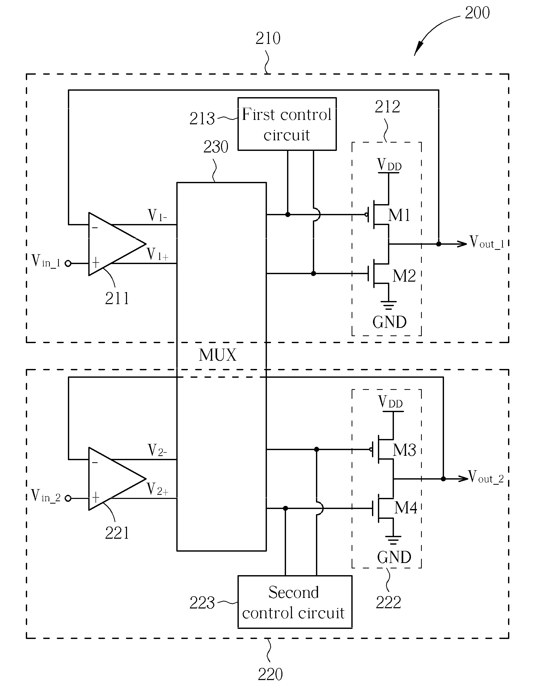
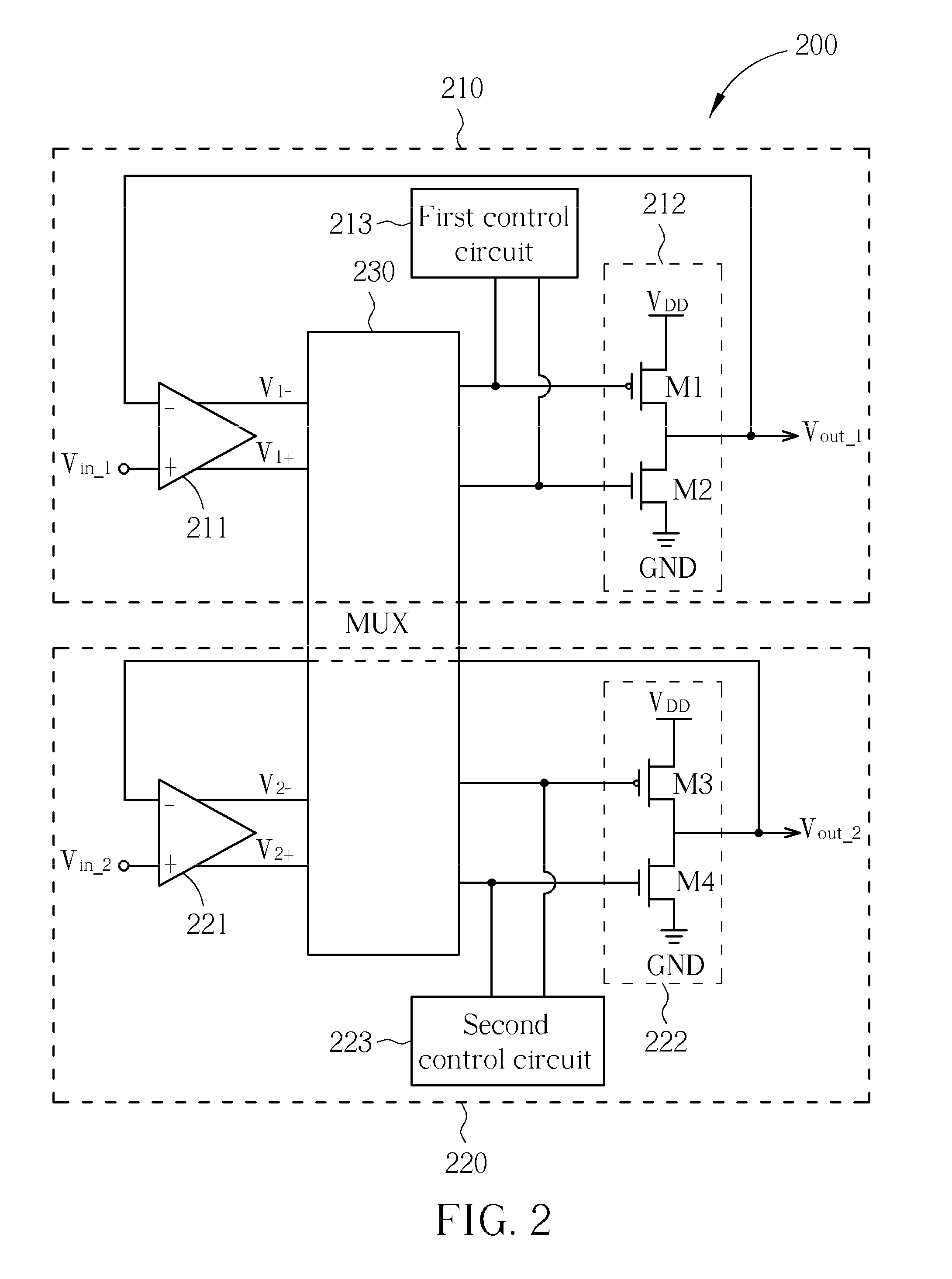
[0014]Please refer to FIG. 2. FIG. 2 is a diagram illustrating a source driver 200 according to one embodiment of the present invention. As shown in FIG. 2, the source drive...


PUM


Abstract

A source driver includes a first differential amplifier, a first output stage, a second differential amplifier, a second output stage and a multiplexer. The first differential amplifier is utilized for receiving a first differential input signal pair to generate a first differential output signal pair. The second differential amplifier is utilized for receiving a second differential input signal pair to generate a second differential output signal pair. The multiplexer couples the first differential amplifier to the first output stage and couples the second differential amplifier to the second output stage under a first configuration, and couples the first differential amplifier to the second output stage and couples the second differential amplifier to the first output stage under a second configuration.

Description

BACKGROUND OF THE INVENTION[0001]1. Field of the Invention[0002]The present invention relates to a source driver, and more particularly, to a source driver which has better driving ability without increasing the chip area, and an associated driving method.[0003]2. Description of the Prior Art[0004]In a source driver of a thin film transistor liquid crystal display (TFT-LCD), a multiplexer is usually positioned after the output buffer of the source driver shown in FIG. 1 for providing high impedance and polarization inversion. FIG. 1 shows two output buffers 102, 104, and a multiplexer 106 of a source driver, where the output buffers 102, 104 have input nodes Nin_1, Nin_2, respectively, and the multiplexer 106 has two output nodes Nout_1 and Nout_2. In FIG. 1, the multiplexer 106 provides an equivalent resistor coupled between the output buffers 102, 104 and the output nodes Nout_1, Nout_2, and the driving ability of the source driver will be influenced. In addition, to prevent from ...

Claims


Application Information

Patent Timeline
IPC IPC(8): G06F3/038
CPCG09G3/3685G09G2310/0291H03F3/45475H03F3/68H03F3/72H03F2203/45726H03F2203/7206H03F2203/7215H03F2203/7221H03F2203/45724H03F2200/414
Inventor WU, JIA-HAO
Owner HIMAX TECH LTD
Why Eureka
Try Eureka