3D image display device

a display device and 3d image technology, applied in the field of 3d image, can solve the problems of adversely affecting the transmittance of 3d image, and achieve the effect of improving the response time of liquid crystals and increasing display quality

Inactive Publication Date: 2011-06-30
LG DISPLAY CO LTD
View PDF17 Cites 37 Cited by
  • Summary
  • Abstract
  • Description
  • Claims
  • Application Information

AI Technical Summary

Benefits of technology

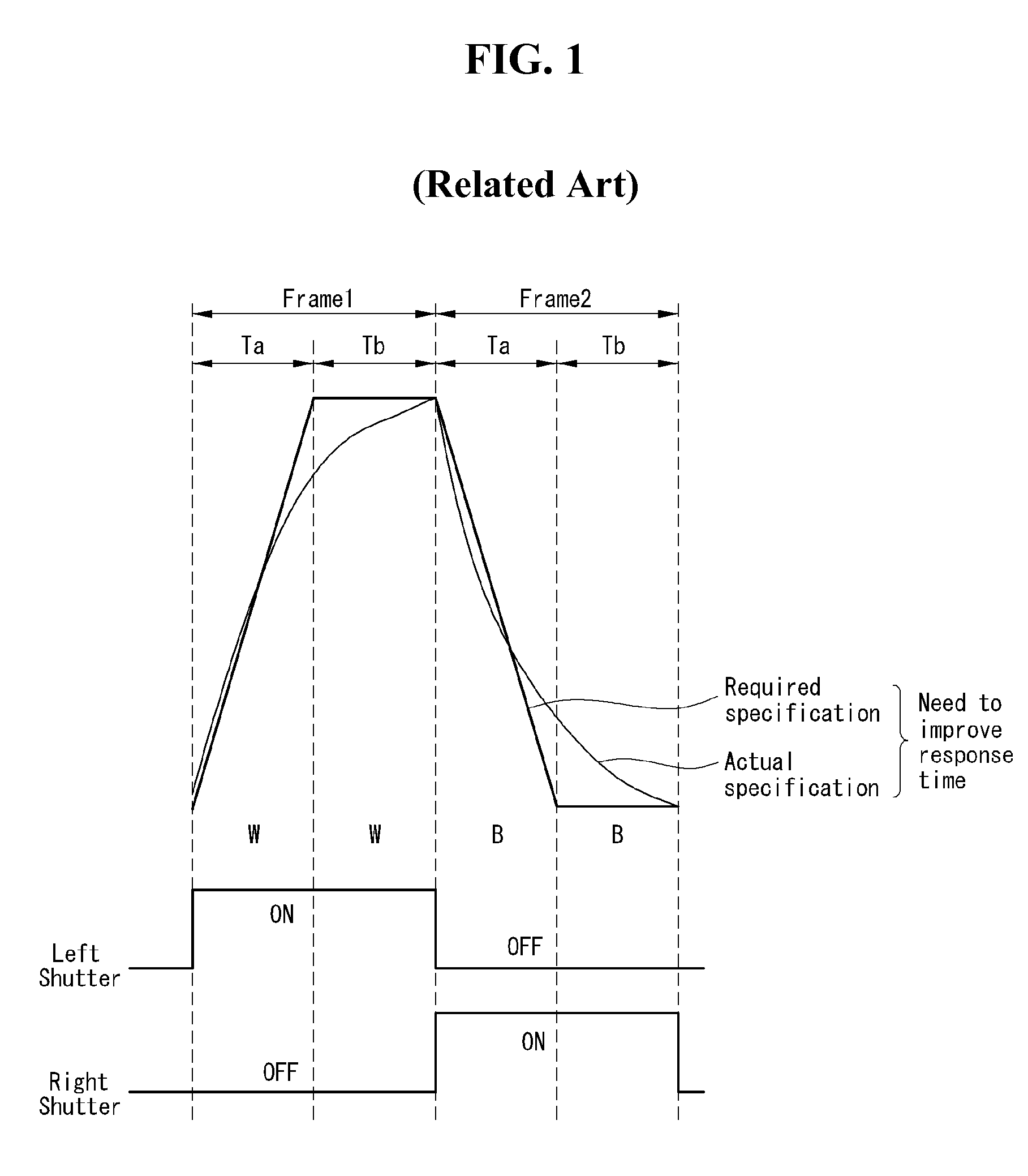
[0011]An aspect of this invention is to provide a 3D image display device which is capable of increasing the display quality by improving the response time of the liquid crystals.

Problems solved by technology

In the first and second polarization filter methods, the pattern retarder film or the switching liquid crystal layer disposed on the liquid crystal panel as a polarization filter may adversely affect the transmittance of a 3D image.

Method used


Image

  • 3D image display device
  • 3D image display device
  • 3D image display device

Examples


first embodiment

[0043]3D cross-talk can be reduced by improving the response time of the liquid crystal display panel using the first embodiment shown in FIGS. 3-5. Nevertheless, the liquid crystal cells in the lower portion of the liquid crystal display panel can still remain in a transition state while the liquid crystal cells in the middle portion of the liquid crystal display panel are in a saturated state because the liquid crystal cells in the lower portion respond to data that is input at a time later than that of the middle portion of the liquid crystal display panel. This is because the turn-on time is determined based on the middle portion of the liquid crystal display panel and because the unit frame period is relatively short, e.g., 1 / 120 seconds when the unit frame frequency is 120 Hz. In order to reduce 3D cross-talk at all portions of the liquid crystal display panel, a longer period must be set aside for all liquid crystal cells, including the cells in the lower portion of the liqui...

second embodiment

[0049]3D cross-talk can be reduced by improving the response time of the liquid crystal display panel using the second embodiment shown in FIGS. 6-8. Accordingly, even if the turn-on time is determined based on the middle portion of the liquid crystal display panel, 3D cross-talk can be eliminated in all portions of the liquid crystal display panel. This is because the unit frame period is relatively long, i.e., 1 / 80 seconds, which provides a longer period for all liquid crystal cells, including the cells in the lower portion of the liquid crystal display panel, to become saturated.

[0050]FIG. 9 is a diagram illustrating an example in which the levels of a driving current are controlled according to the duty ratio of a PWM signal in order to compensate for a reduction in brightness. As shown in FIG. 9, the level of the driving current is inversely proportional to the maximum duty ratio of the PWM signal. For example, when the reference current level A is defined to be the current lev...


PUM


Abstract

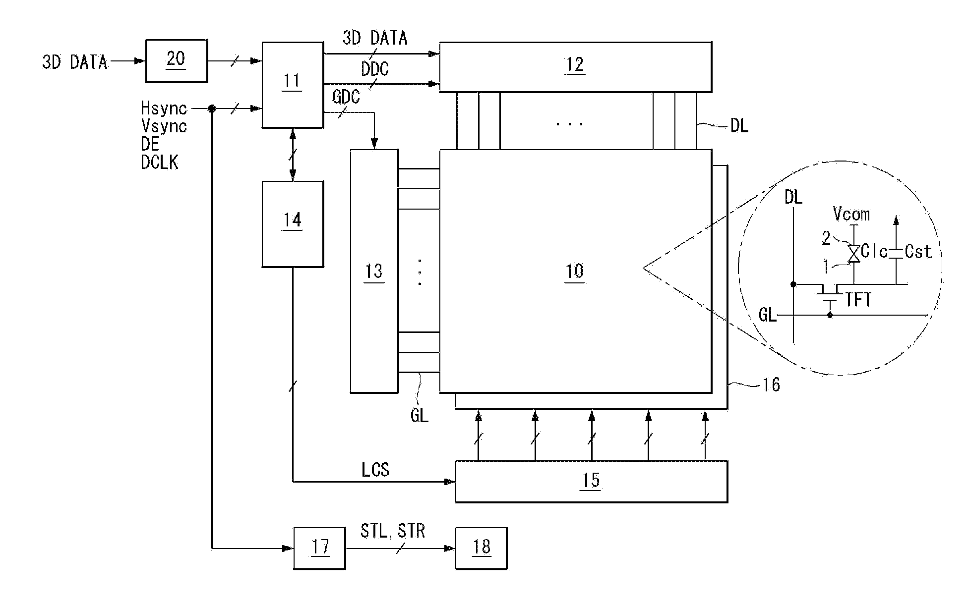
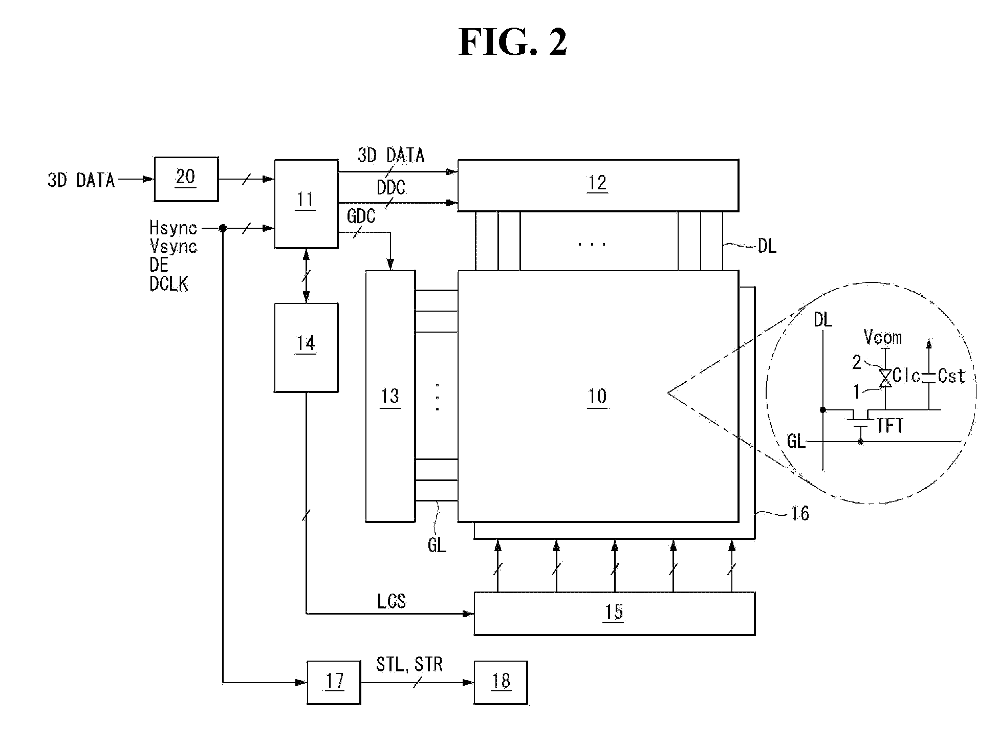
A 3-dimensional (3D) image display device includes a liquid crystal panel configured to alternately display a left-eye image and a right-eye image in a cycle of unit frame period, a data driving circuit configured to drive data lines of the liquid crystal panel, a gate driving circuit configured to drive gate lines of the liquid crystal panel, a timing controller configured to divide the unit frame period into N sub-frame periods for each of the left-eye image and the right-eye image, where N is an integer equal to or greater than 2, a plurality of light sources configured to generate light to be radiated to the liquid crystal panel, a light source control circuit configured to generate a backlight control signal to control a turn-on time of the plurality of light sources, and a light source driving circuit configured to turn off all the light sources during a first N-1 subframe periods and turn on all the light sources during a last subframe period.

Description

[0001]This application claims the benefit of Korean Patent Application No. 10-2009-0134638 filed on Dec. 30, 2009 and Korean Patent Application No. 10-2010-0030382 filed on Apr. 2, 2010, which are hereby incorporated by reference.BACKGROUND OF THE INVENTION[0002]1. Field of the Invention[0003]The present invention relates to an image display device, and more particularly to a 3-dimensional image (hereinafter referred to as “3D image”) display device which is capable of increasing the display quality by improving the response time of liquid crystals.[0004]2. Discussion of the Related Art[0005]A 3D image display device implements a 3D image using a stereoscopic technique or an autostereoscopic technique. The 3D image display device uses parallax images of the left and right eyes having a high 3D effect and comprises a stereoscopic technique and an autostereoscopic technique, both of which are being put to practical use. In the autostereoscopic technique, in general, an optical plate, ...

Claims


Application Information

Patent Timeline
Patent Type & Authority Applications(United States)
IPC IPC(8): G09G3/36G09G5/10
CPCG02B27/2264G09G3/3406G09G3/3688G09G2310/0237H04N13/0497G09G2320/0209G09G2320/0252G09G2320/0646H04N13/0438G09G2310/06H04N13/341H04N13/398G02B30/24
Inventor PYUN, JAYOUNGKIM, KIDUKSEO, BOGUN
Owner LG DISPLAY CO LTD
Why Eureka
Try Eureka