Primary side sensing for isolated fly-back converters

a fly-back converter and side sensing technology, applied in the field of isolated switching voltage converters, can solve the problems of side sensing approaches that have had problems with accurately determining the fly-back voltage, and the use of optocouplers for feedback has additional components and pcb area spa

Active Publication Date: 2011-06-30
SILICON LAB INC
View PDF24 Cites 39 Cited by
  • Summary
  • Abstract
  • Description
  • Claims
  • Application Information

AI Technical Summary

Problems solved by technology

The use of an opto-coupler for feedback has costs such as additional components as well as PCB area space.
However prior art primary side sensing approaches have had problems with accurately determining the flyback voltage.

Method used


Image

  • Primary side sensing for isolated fly-back converters
  • Primary side sensing for isolated fly-back converters
  • Primary side sensing for isolated fly-back converters

Examples


Embodiment Construction

)

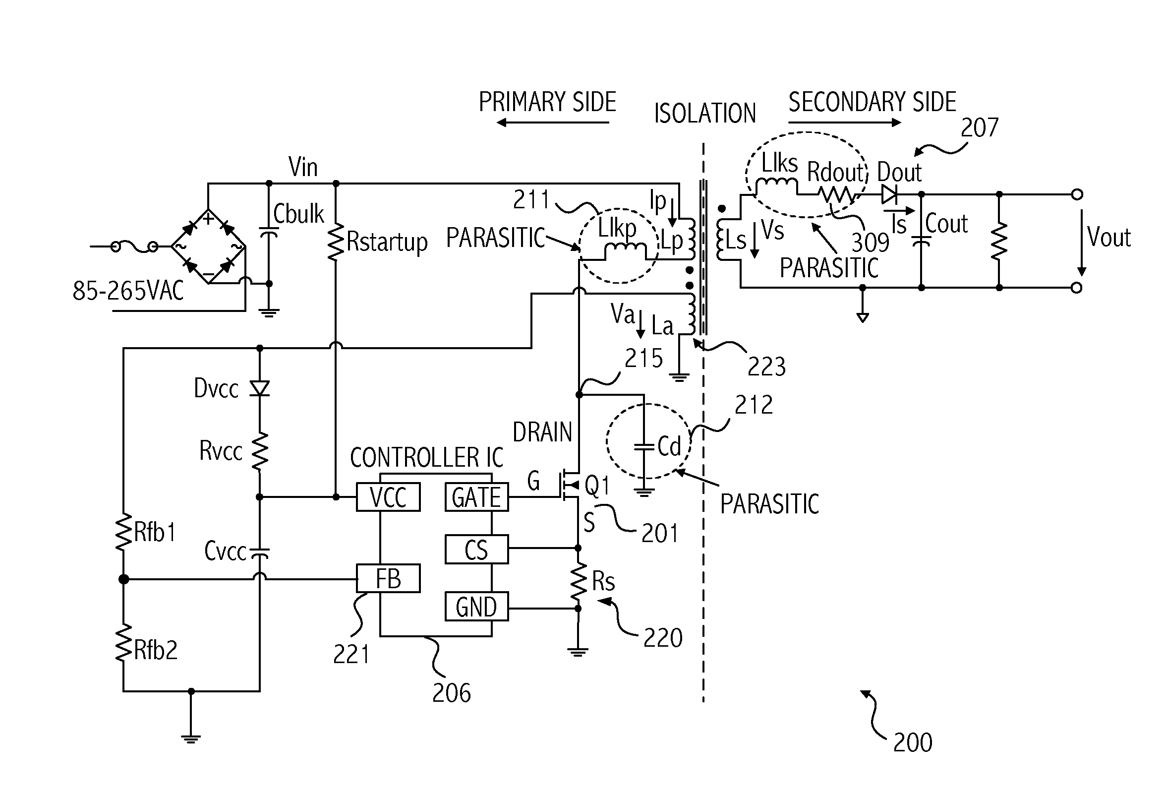
[0027]Referring to FIG. 2, illustrated is a high level diagram of a switching voltage regulator 200 incorporating an embodiment of the invention that senses flyback voltage in a manner that provides output voltage regulation accuracy while avoiding most errors, mainly due to external parasitic impedances. The switching voltage regulator 200 includes a controller integrated circuit 206 that provides appropriate processing for the flyback voltage according to an embodiment of the invention. The circuit providing the flyback processing can be implemented in plain digital CMOS processes, and since it has a small digital logic content, occupies a small silicon area even in an older and larger feature size CMOS process.

[0028]The power MOSFET switch 201 turns ON (TON phase) and OFF (TOFF phase) according to the gate control signal supplied by the controller integrated circuit 206. An auxiliary winding 223 is coupled to the feedback (FB) pin 221 of integrated circuit 206. That auxiliary wi...


PUM


Abstract

A switching voltage regulator samples signals corresponding to a flyback voltage on an auxiliary winding on a primary side of the switching voltage regulator. The flyback voltage functions as feedback from the output voltage on the secondary side. On detection of presence of the flyback voltage, samples corresponding to the flyback voltage are stored until the flyback voltage falls below a threshold voltage. A history of N samples of the flyback voltage is thus maintained. A sample older than the most recently stored sample is used to generate control for generation of the output voltage of the switching voltage regulator. Use of the older sample ensures that the flyback voltage sample used is one that is close to, but before the current in the secondary winding goes to zero.

Description

BACKGROUND[0001]1. Field of the Invention[0002]The present invention is directed to isolated switching voltage converters and more particularly to primary side sensing of the output voltage on the secondary side of a switching voltage converter.[0003]2. Description of the Related Art[0004]Switching voltage converters (also referred to herein as switching voltage regulators) are used to provide, e.g., regulated DC output voltage from an unregulated AC input. Typical consumer products involving such switching regulators include cell phone chargers, laptop or printer power supplies (so-called “bricks”), and embedded PC power supplies.[0005]FIG. 1 illustrates a switching regulator 100 having a flyback topology commonly used in power supplies with output power less than 200 W. The illustrated topology is suitable for discontinuous current mode (DCM) operation in which the transformer core is fully demagnetized in each cycle. Another mode of operation is continuous current mode (CCM).[000...

Claims


Application Information

Patent Timeline
Patent Type & Authority Applications(United States)
IPC IPC(8): H02M3/335
CPCH02M3/33515
Inventor KONECNY, PAVELYEDEVELLY, YESHODA
Owner SILICON LAB INC
Why Eureka
Try Eureka