

Power adapter apparatus and power management method
a technology of power management and power adapter, which is applied in the direction of electric variable regulation, process and machine control, instruments, etc., can solve the problems of wasting energy, certain degree of static power consumption, and the inability of the household power source to be applied directly on these electronic devices
- Summary
- Abstract
- Description
- Claims
- Application Information
AI Technical Summary
Benefits of technology
Problems solved by technology
Method used
Image

Examples
first embodiment
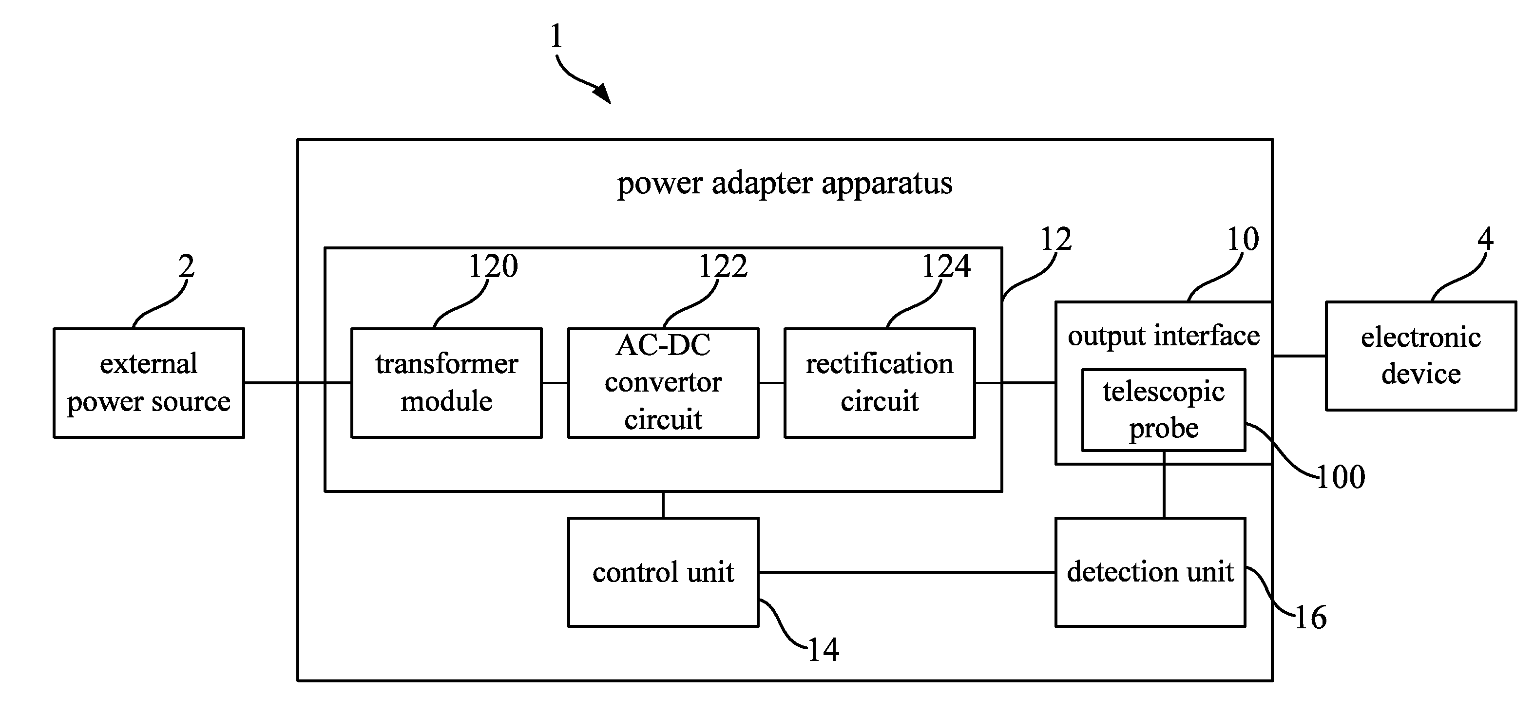
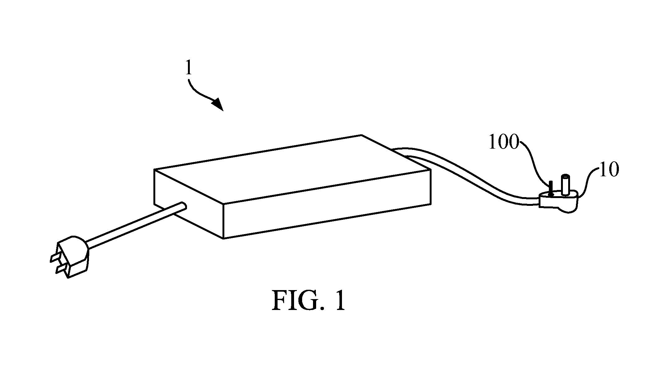
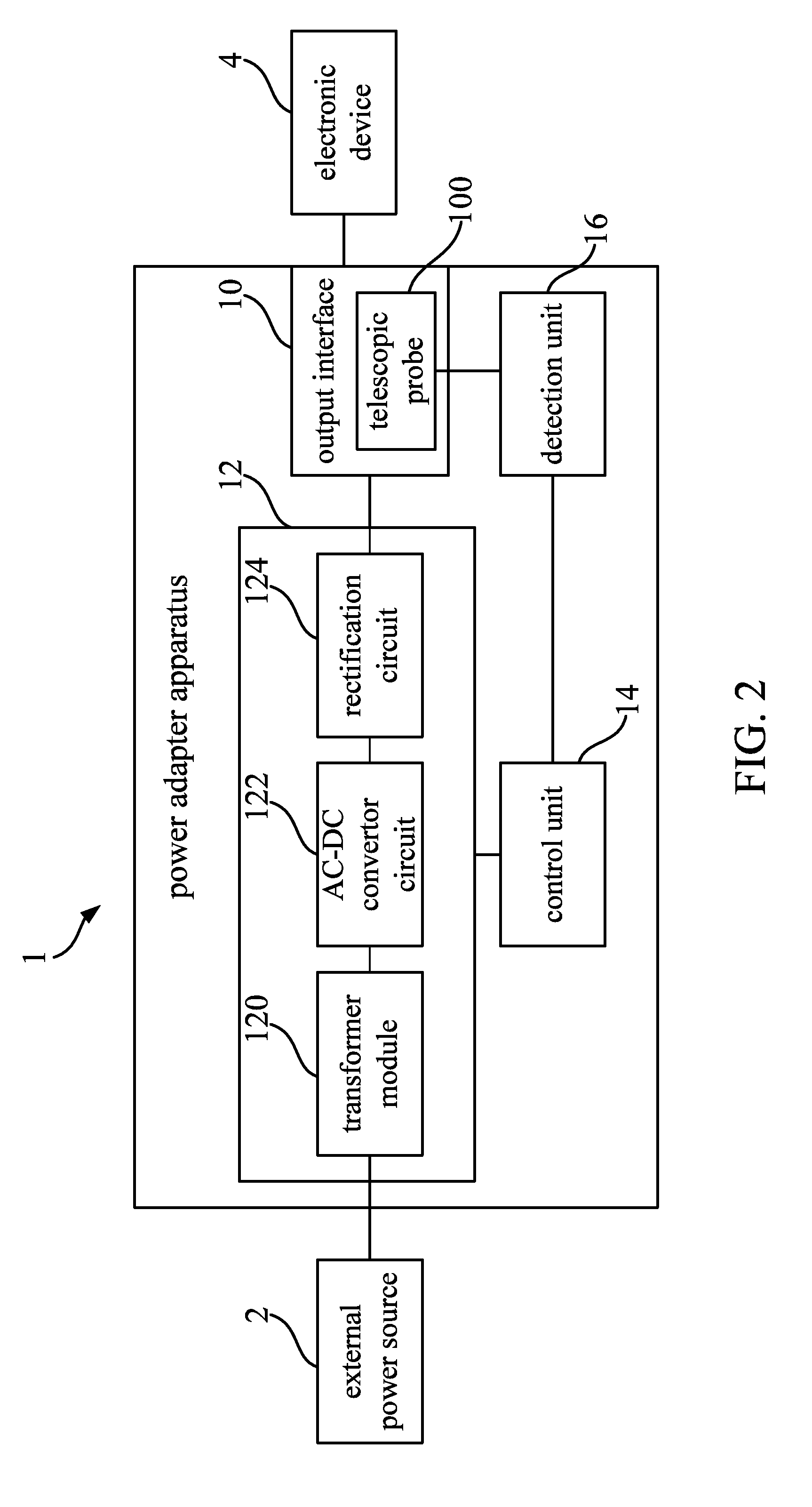
[0029]Please refer to FIG. 1 and FIG. 2. FIG. 1 is an outside view illustrating a power adapter apparatus 1 according to the invention. FIG. 2 is a functional block diagram illustrating the power adapter apparatus 1 in FIG. 1. In the embodiment, the power adapter apparatus 1 includes an output interface 10, a power modulation unit 12, a control unit 14 and a detection unit 16.
[0030]As shown in FIG. 1, there is a telescopic switch 100 on a surface of the output interface 10. In this case, the telescopic switch 100 is movably disposed on the surface of the output interface 10. The telescopic switch 100 can be shaped as a telescopic probe shown in FIG. 1, but the invention is not limited to this. In practical applications, there may be a flexible component (such as spring, metal sheet or rubber pad) disposed under the telescopic switch 100 for providing the flexibility.
[0031]The power modulation unit 12 is electrically connected to an external power source 2. The power modulation unit ...
second embodiment
[0039]Please refer to FIG. 3 and FIG. 4. FIG. 3 is an outside view illustrating the power adapter apparatus 3 according to the invention. FIG. 4 is a functional block diagram illustrating the power adapter apparatus 3 in FIG. 3.
[0040]The power adapter apparatus 3 includes an output interface 30, a power modulation unit 32, a control unit 34 and a detection unit 36. The main difference from the first embodiment is that there is an extra detective node 300 disposed on the original power supply pin of the output interface 30 in this embodiment. As shown in FIG. 3, the detective node 300 can be the extra rod-shaped pin disposed in-between the original power supply pin. In practical applications, the detective node may also be a ring-shaped pin disposed around the original power supply pin, or any pin other than the original power supply pin in any shape. The way to implement an extra contact point for the detective node is well known by a person in the art, so not to be further mentione...
third embodiment
[0049]Please refer to FIG. 6. FIG. 6 is a flow chart illustrating the power management method according to the invention. As shown in FIG. 6, step S100 of the power management method is executed to utilize the detective structure for detecting whether the power adapter apparatus is electronically connected to the electronic device or not.
[0050]When the output interface is detected to be disconnected from the electronic device, step S102 is executed to switch the power modulation unit into a standby state, for reducing a total power consumption of the power modulation unit.
[0051]On the other hand, when the output interface is detected to be electrically connected to the electronic device, step S104 is executed to switch the power modulation unit into a working state, such that the power modulation unit is utilized to modulate on the external power source and supply electricity to the output interface for driving the electronic device.
[0052]In other words, the power adapter apparatus ...
PUM
 Abstract
Description
Claims
Application Information