Extraordinary light transmission apparatus and method

a technology of light transmission apparatus and light transmission method, applied in the field of optical instruments, can solve the problem of low transmission rate, achieve the effect of enhancing (extraordinary) light transmission and transmission through a sub-wavelength aperture of finite depth

Active Publication Date: 2011-06-30
CORNELL UNIVERSITY
View PDF14 Cites 10 Cited by
  • Summary
  • Abstract
  • Description
  • Claims
  • Application Information

AI Technical Summary

Benefits of technology

[0010]An embodiment of the invention is an optical apparatus that provides enhanced (extraordinary) light transmission through a sub-wavelength-sized light transmitting region of the apparatus herein referred to as the ‘core region’ of the apparatus. Most generally, the optical apparatus includes a core region of dielectric material having a complex dielectric constant, ε1, surrounded by a metallic cladding material having a complex dielectric constant, ε2, wherein the core region has a maximum dimension, 2a, further wherein 2a is less than λ, where λ is the free-space wavelength of light incident on an input side of the apparatus, and further wherein |ε1| is greater than 0.5|ε2|, ε1 has a positive real part, and ε2 has a negative real part, whereby the incident light will be transmitted by and exit the apparatus from an output side with extraordinary transmission. According to a non-limiting, exemplary aspect, the optical apparatus may be in the form of a nanoscopic near-field scanning waveguide probe that includes a commercially available tapered fiber and, an inventive probe end coupled to the tapered fiber, wherein the probe end comprises a core region as described above and wherein the cladding material has a wall thickness, tw, where (2a+2tw) is less than 100 nanometers (nm). According to another non-limiting, exemplary aspect, the optical apparatus may be in the form of a (thin) sheet of the cladding material having a thickness, d, including a core region of maximum dimension 2a, wherein 2a<d and, more particularly, 2a≦0.5d. In a non-limiting exemplary aspect, the sheet thickness d has a value such that the apparatus provides a Fabry-Pérot resonance wherein the transmitted light undergoes a round trip phase shift, φF-P, where φF-P is an integer multiple of 2π. Transmission through a sub-wavelength aperture of finite depth can be enhanced when the depth of the aperture is such that Fabry-Pérot-like resonances are excited. For example, for 810 nm light incident on a silicon-filled 50-nm-diameter aperture in a 200-nm-thick gold film, we observed a normalized near-field intensity ratio of 1.6 at the exit. Non-limiting exemplary applications of this resonantly enhanced transmission phenomenon include near-field scanning optical microscopy and single-molecule spectroscopy. In various non-limiting aspects, the sheet may be flat, and the sheet may include a plurality of discrete core regions arranged, for example, in an array. In various non-limiting aspects, the core region may have a cross sectional geometrical shape of a circle, an oval, a slit, a plurality of connected slits, a C, a C including a protrusion, an H, an E, a square or rectangle, and others. In various non-limiting aspects, the cladding regions of the sheet may be textured or otherwise have a desired topography as reported in the art. In a non-limiting aspect, the sheet form of the optical apparatus may further include a first medium having a dielectric constant, ε3, disposed immediately adjacent the input side of the apparatus and a second medium having a dielectric constant, ε4, disposed immediately adjacent the output side of the apparatus. One or both of the first and second media may be solid or fluidic (including gaseous).

Problems solved by technology

While enhanced transmission can be achieved in some of the reported scanning probe designs with novel aperture shapes, the large overall probe sizes used in these designs make them undesirable, particularly for imaging delicate samples.
However, for wavelengths above the cutoff, transmission is still very low because no propagating modes are allowed inside the aperture.

Method used


Image

  • Extraordinary light transmission apparatus and method
  • Extraordinary light transmission apparatus and method
  • Extraordinary light transmission apparatus and method

Examples


Embodiment Construction

[0019]Reference will now be made in detail to the present exemplary embodiments of the invention, non-limiting examples of which are illustrated in the accompanying drawings. Wherever possible, the same reference numbers will be used throughout the drawings to refer to the same or like parts.

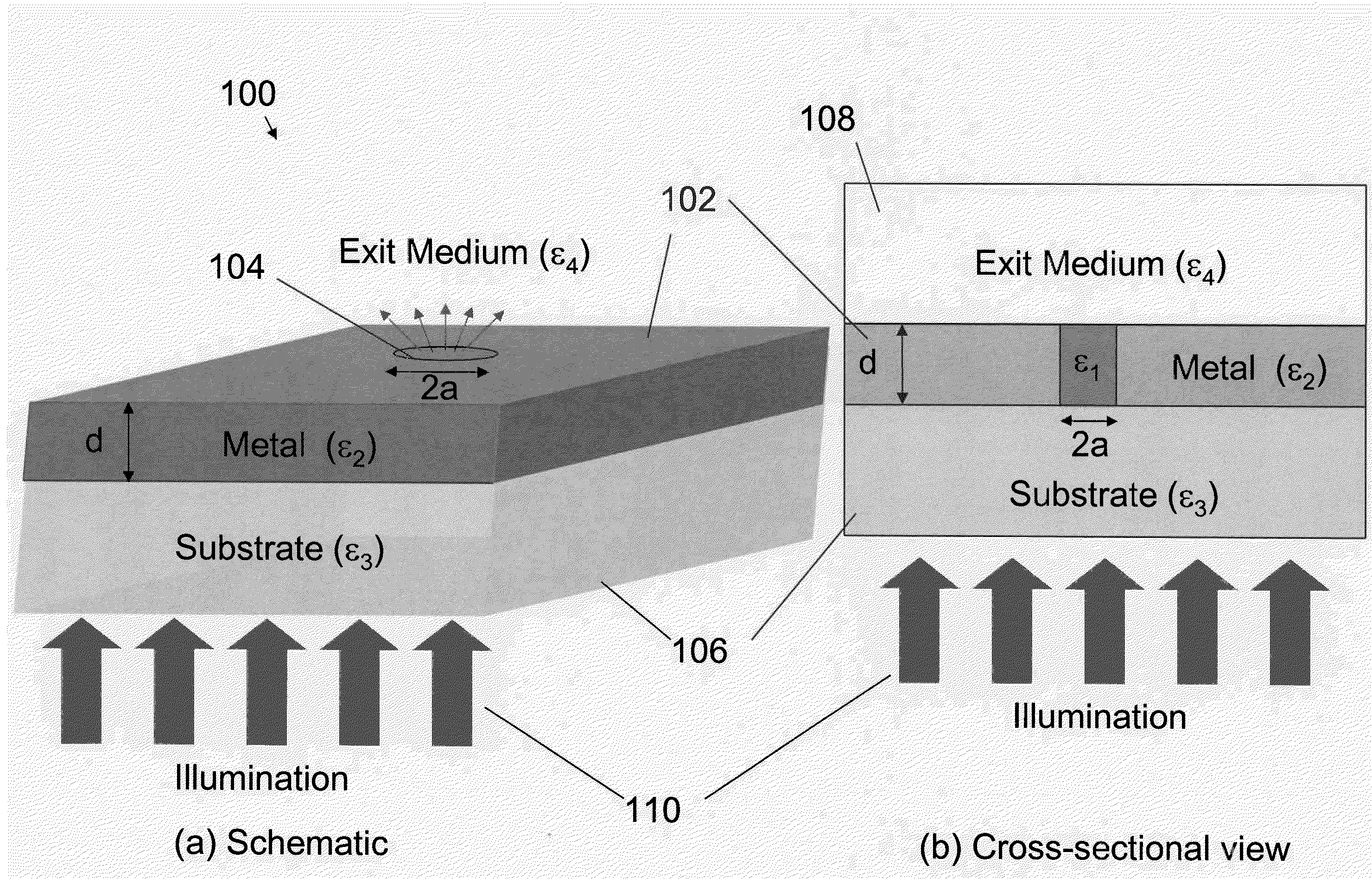
[0020]The metallic cladding material component of the invention disclosed herein is intended to be a “real metal,” which means a metal material having a complex dielectric constant whose real part is a finite negative number, in contrast to “a perfectly conducting metal” where the metal's conductivity is assumed (e.g., by physicists) for simplicity to be infinite. For example, at wavelength 810 nm, gold has a dielectric constant of −24.89+1.57i. Thus the conductivity of a ‘real metal’ is always finite; i.e., no metal is a perfect conductor. As a result of finite conductivity, electric fields can penetrate into metals and exist in a thin layer beneath the metal surface.

[0021]As used herein and as...


PUM

PropertyMeasurementUnit
thicknessaaaaaaaaaa
thickaaaaaaaaaa
diameteraaaaaaaaaa

Abstract

An optical apparatus that provides extraordinary light transmission through a sub-wavelength-sized light transmitting region of the apparatus includes a core region of dielectric material having a complex dielectric constant, ε1, surrounded by a metallic cladding material having a complex dielectric constant, ε2, wherein the core region has a maximum dimension, 2a, further wherein 2a is less than λ, where λ is the free-space wavelength of light incident on an input side of the apparatus, and further wherein |ε1| is greater than 0.5|ε2|, ε1 has a positive real part, and ε2 has a negative real part, whereby the incident light will be transmitted by and exit the apparatus from an output side with extraordinary transmission.

Description

CROSS-REFERENCE TO RELATED APPLICATIONS[0001]This application claims priority to U.S. provisional Patent Application Ser. No. 61 / 291,201 filed on Dec. 30, 2009, the content of which is incorporated herein by reference in its entirety.FEDERALLY SPONSORED RESEARCH[0002]This invention was made with Government support under grant ECS 9876771 awarded by NSF and grant 5 P41 EB001976-20 awarded by NIH. The United States Government has certain rights in the invention.BACKGROUND OF THE INVENTION[0003]1. Field of the Invention[0004]Embodiments of the present invention relate generally to the field of optics; more particularly to optical apparatus, methods and applications that provide and utilize the phenomena of extraordinary transmission of light through a sub-wavelength-sized aperture and, most particularly to the extraordinary transmission of light through a dielectric-filled aperture(s) in a real metal film.[0005]2. Technical Background[0006]Ebbesen et al. reported the discovery of extra...

Claims


Application Information

Patent Timeline
Patent Type & Authority Applications(United States)
IPC IPC(8): G02F1/035
CPCG02B27/0087B82Y20/00B82Y35/00G01Q60/22G11B7/1387G02B6/107G02B27/58G02B6/262G02B1/118
Inventor CRAIGHEAD, HAROLD G.WEBB, WATT W.XU, HUIZHONGZHU, PANGSHUN
Owner CORNELL UNIVERSITY
Why Eureka
Try Eureka