
Handheld electric power tool

a power tool and hand-held technology, applied in the field of hand-held power tools, can solve the problems of inconvenient use, large battery pack of electric power tools, and heavy weight of power tools, and achieve the effect of improving the weight distribution and reducing the weight of power tools

Inactive Publication Date: 2011-07-07
MAKITA CORP
View PDF28 Cites 58 Cited by
  • Summary
  • Abstract
  • Description
  • Claims
  • Application Information

AI Technical Summary

Benefits of technology

[0005]Accordingly, it is an object of the present teachings to provide a technique for improving the weight distribution with respect to the top grip or the top handle.
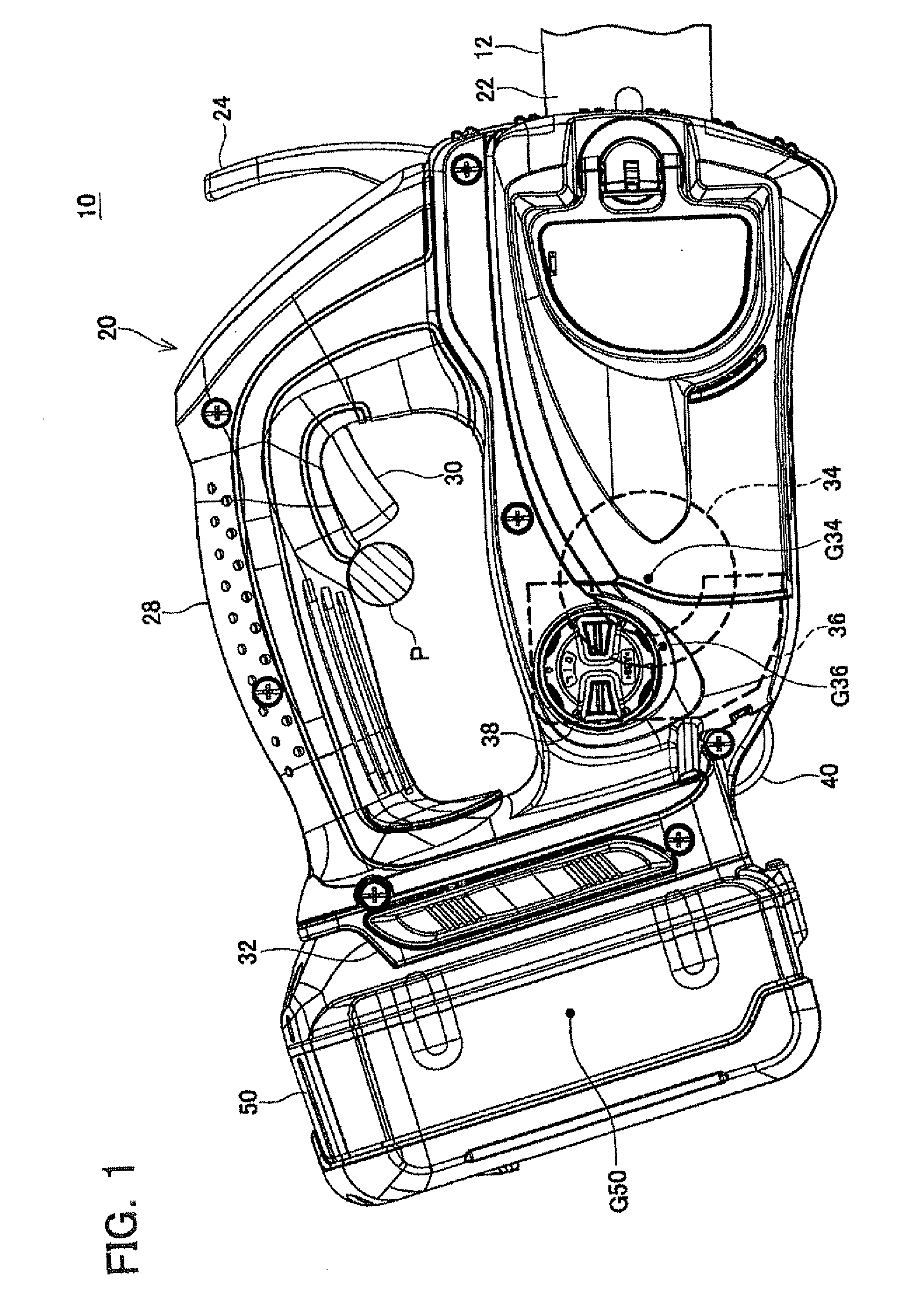
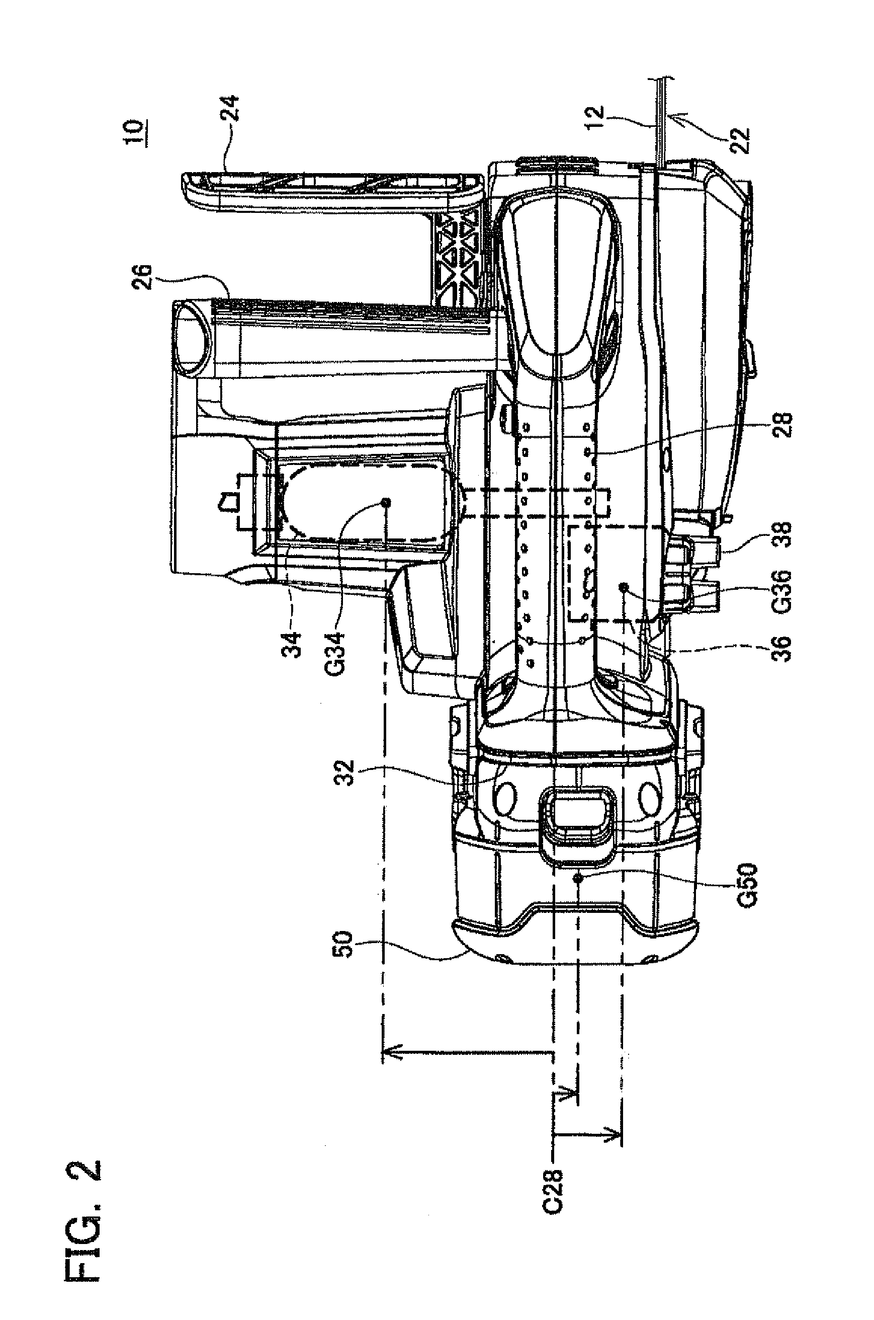
[0006]Generally, a battery pack for an electric power tool is large and heavy. Therefore, the conventional power tool is designed such that, in a planar view of the main body, the center of gravity of the battery pack is located on a straight line passing through the center axis of the top grip. With this design, the heavy battery pack is prevented from influencing the weight distribution of the power tool with respect to the top grip.
[0007]On the contrary, the present teachings proposes a new design in which the battery pack is arranged to be horizontally displaced with respect to the center axis of the top grip. With this design, the weight distribution of the power tool may be drastically improved by using the heavy weight of the battery pack such that the center of gravity of the power tool is located on the straight line passing through the center axis of the top grip.

Problems solved by technology

Such imbalance causes inconvenience to the user.
Generally, a battery pack for an electric power tool is large and heavy.

Method used


Image

  • Handheld electric power tool
  • Handheld electric power tool
  • Handheld electric power tool

Examples


embodiment

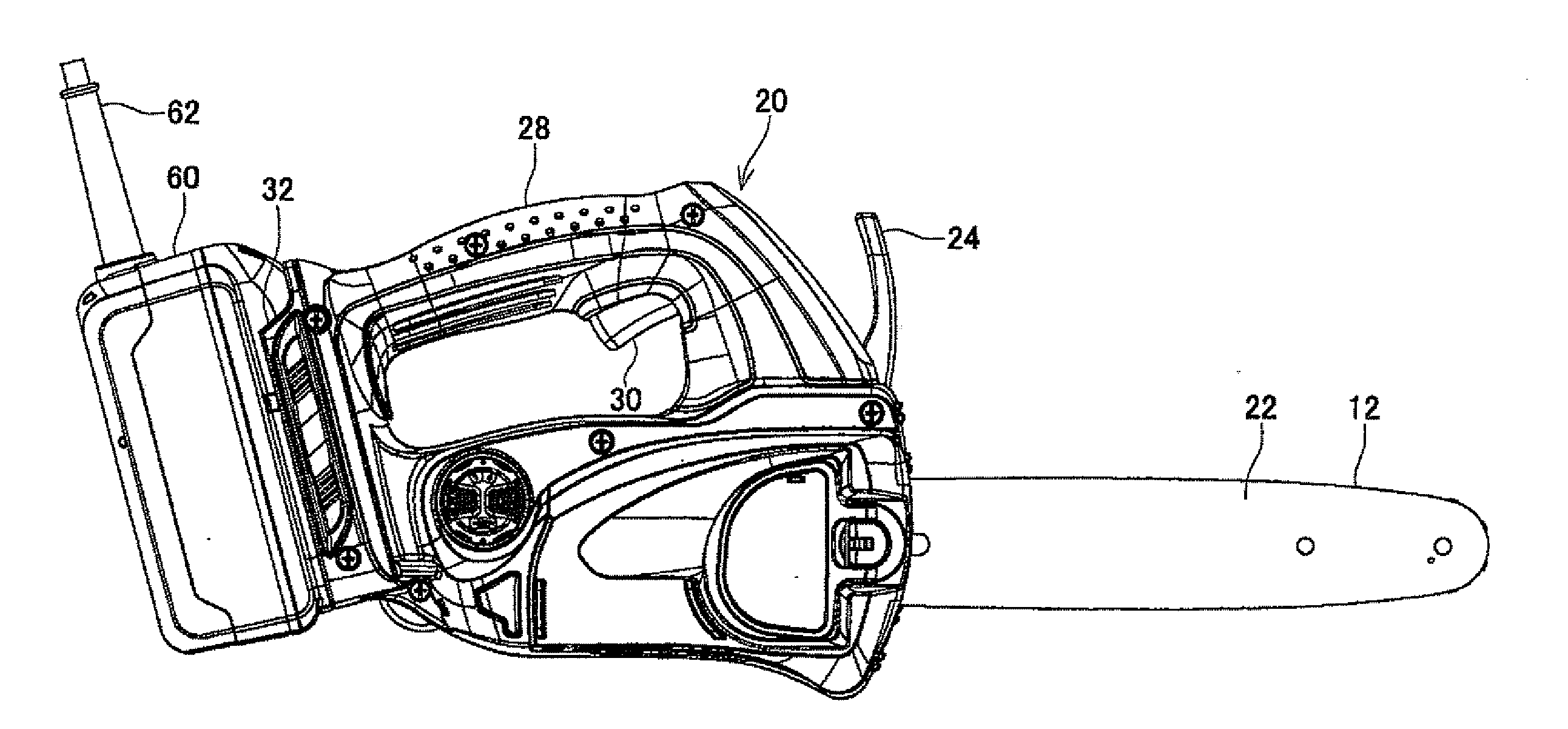
[0027]Referring the drawings, a chain saw 10 of a specific embodiment will be described below. The chain saw 10 of the present embodiment is a type of handheld electric power tool for cutting a timber. As shown in FIGS. 1 and 2, the chain saw 10 is provided with a saw chain 12 and a main body 20 for driving the saw chain 12 to turn. The saw chain 12 has a plurality of small blade edges (not shown), and cuts a timber by contacting while turning.

[0028]The main body 20 is provided with a guide bar 22. The guide bar 22 extends frontward (rightward in FIGS. 1 and 2) from the main body 20. The saw chain 12 is arranged around the guide bar 22 and the guide bar 22 supports the saw chain 12 in a manner of allowing the saw chain to turn. The saw chain 12 is arranged around not only the guide bar 22 but also a sprocket (not shown) housed in the main body 20. Such configuration is the same as conventional chain saws and the chain saw 10 of the present embodiment is not limited to a specific con...


PUM

PropertyMeasurementUnit
Gravityaaaaaaaaaa

Abstract

A handheld electric power tool comprises a main body supporting a tool, a motor housed in the main body and configured to drive the tool, a battery interface disposed in a back portion of the main body and configured to detachably receive a battery pack, and a top grip disposed on a top portion of the main body. In a planar view of the main body, a center axis of the top grip extends in front and back direction and a center of gravity of the battery pack attached to the battery interface is located at one side of a straight line passing through the center axis of the top grip.

Description

CROSS-REFERENCE TO RELATED APPLICATION[0001]This application claims priority to Japanese Patent Application No. 2010-000124 filed on Jan. 4, 2010, the contents of which are hereby incorporated by reference into the present application.TECHNICAL FIELD[0002]The present application relates to handheld power tools that include, but are not limited to, electric chain saws, electric circular saws and electric blowers. Especially, the present application relates to a type of handheld power tools with a top grip or a top handle disposed on a top portion of its main body.RELATED ART[0003]JP 2008-55711 A discloses an electric chain saw. The electric chain saw is a type of handheld electric power tools with a top grip. The electric chain saw comprises a saw chain and a main body having a guide bar for the saw chain. A motor is housed in the main body and configured to drive the saw chain. A battery interface configured to detachably receive a battery pack is disposed in a back portion of the m...

Claims


Application Information

Patent Timeline
IPC IPC(8): B27B17/02B25F5/02
CPCB25F5/02B27B17/00
Inventor OKOUCHI, KATSUMI
Owner MAKITA CORP
Learn More