Firearm mount with embedded sight

a technology of embedded sight and mount, which is applied in the direction of sighting devices, weapons, cartridge extractors, etc., can solve the problems of occupying more space for the receptor used for engaging the rail, and reducing the offset of the laser sight. , the effect of reducing the size of the accessory moun

Active Publication Date: 2011-07-07
CROSMAN CORP
View PDF30 Cites 81 Cited by
  • Summary
  • Abstract
  • Description
  • Claims
  • Application Information

AI Technical Summary

Benefits of technology

[0011]In one configuration, the present system exploits space occupied by accessory mounts to construct sub-mountings for laser sights for such purposes as minimizing the offset of the laser sights from barrels, protecting the laser sights from exposure to jarring, and reducing encumbrances presented by the laser sights to the safe handling and operation of firearms. The accessory mounts, which p

Problems solved by technology

At close distances, the offset can result in a significant targeting error approximating the initial offset.
However, such built-in mounting locations are not available in all handguns, so laser sights have also been externally mounted from both conventional rails and special adapters.
In addition, the receptors used for

Method used


Image

  • Firearm mount with embedded sight
  • Firearm mount with embedded sight
  • Firearm mount with embedded sight

Examples


Embodiment Construction

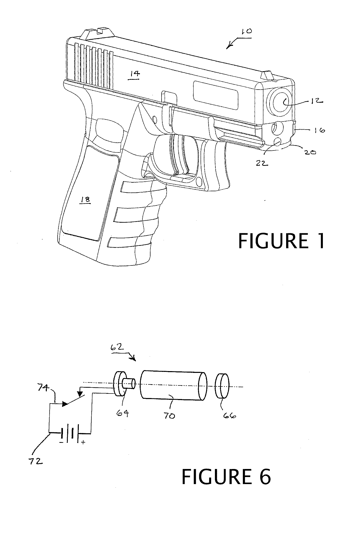
[0055]A small arm dischargeable device, such as a conventional pistol 10 is depicted in FIG. 1, includes the usual features of a barrel 12, a slide 14, and a receiver (or frame) 16 with an integral grip 18 as well as an accessory rail mount 20 such as a primary rail mount which can have any of a variety of configurations such as Picatinny or Weaver. The accessory rail mount 20 extends along a discharge axis of the small arm dischargeable device.

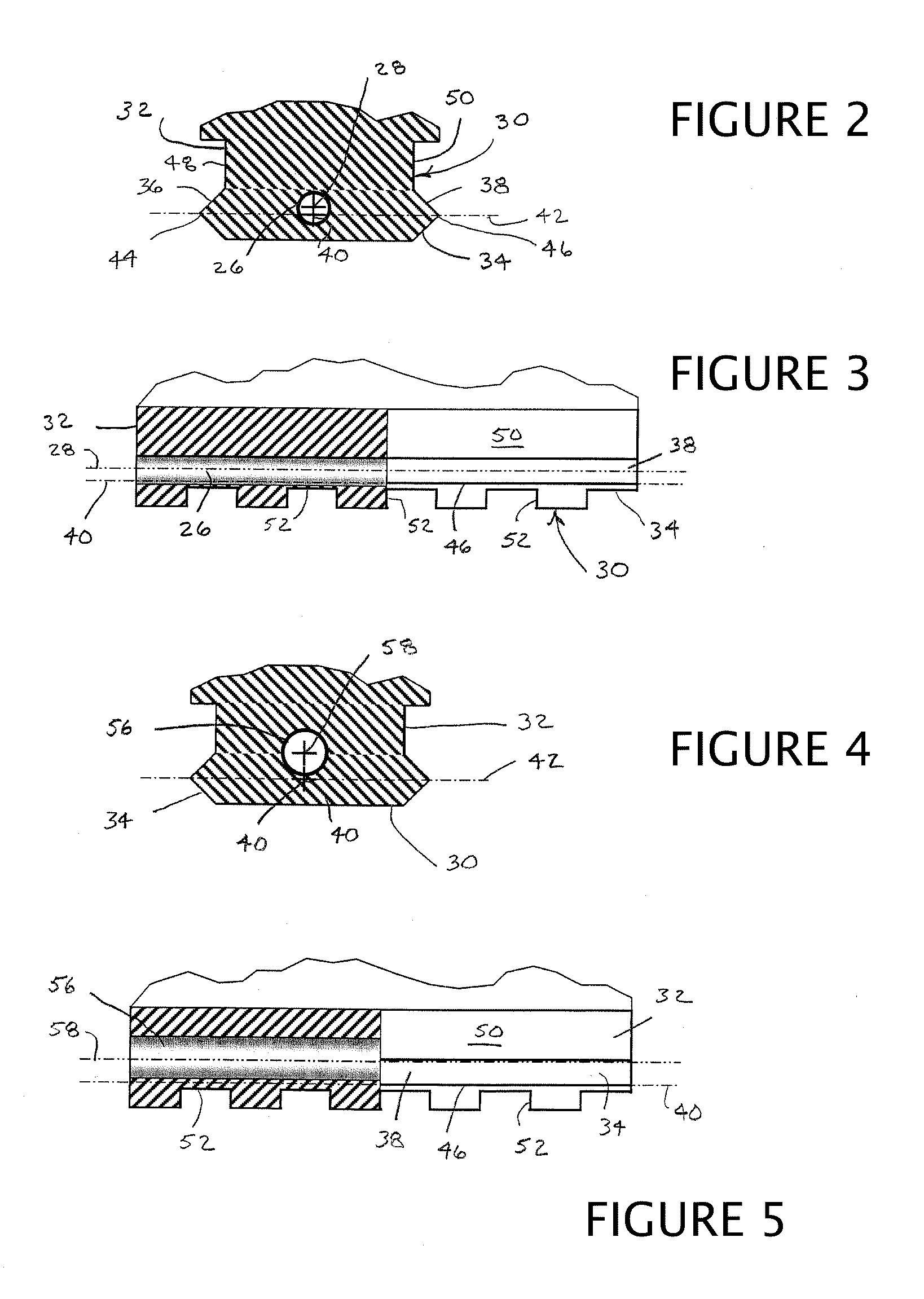
[0056]Referring to FIGS. 2 and 3, an alternative primary rail mount 30 is shown having the conventional configuration of a rail mount with a generally T-shaped profile, thus providing a dovetail such as a Weaver or Picatinny rail. A pedestal 32 (forming the base of the T) supports an overhanging platform 34 (forming the crossbar of the T) that has tapered sidewalls 36 and 38 extending without interruption along a longitudinal axis 40 of the primary rail mount 30. The longitudinal axis 40 is generally aligned with a barrel of a firearm. The ta...


PUM


Abstract

A laser sight is embedded in a mounting rail otherwise used for attaching accessories to small arms discharge devices such as pistols or rifles. The mounting rail has a transverse profile that extends along an axis of the mounting rail for engaging mating features of the accessories. The laser sight is located at least partly within the transverse profile of the mounting rail and has a sighting axis that extends substantially parallel to the axis of the mounting rail.

Description

CROSS-REFERENCE TO RELATED APPLICATIONS[0001]The present application is a continuation in part of U.S. application Ser. No. 12 / 118,105 filed May 9, 2008, published as US Published Patent application 2009 / 0013580 issuing Jun. 29, 2010 as U.S. Pat. No. 7,743,547, which is a division of U.S. application Ser. No. 11 / 307,385 filed Feb. 4, 2006 issuing as U.S. Pat. No. 7,421,818 on Sep. 9, 2008 each of which is expressly incorporated by reference.STATEMENT REGARDING FEDERALLY SPONSORED RESEARCH OR DEVELOPMENT[0002]Not applicable.THE NAMES OF THE PARTIES TO A JOINT RESEARCH AGREEMENT[0003]Not applicable.REFERENCE TO A “SEQUENCE LISTING”[0004]Not applicable.BACKGROUND OF THE INVENTION[0005]1. Field of the Invention[0006]The present invention relates to sights and their mounting on small arm dischargeable devices such as firearms.[0007]2. Background of the Invention[0008]Laser sights are particularly effective as sighting devices because the lasers illuminate spots on their targets and do no...

Claims


Application Information

Patent Timeline
IPC IPC(8): F41G1/34F41C27/00F41G1/35
CPCF41G1/35F41G11/003F41G1/36
Inventor HOUDE-WALTER, WILLIAM R.
Owner CROSMAN CORP
Why Eureka
Try Eureka