
Solar Cell Module and Solar Cell Array

a solar cell and solar panel technology, applied in the direction of photovoltaic supports, sustainable buildings, roofing, etc., can solve the problems of limiting the size of the module and the number of the output voltage of the unit, and achieves easy wiring in the arrangement, uniform configuration, and stable output performance.

Inactive Publication Date: 2011-07-07
KANEKA CORP
View PDF7 Cites 16 Cited by
  • Summary
  • Abstract
  • Description
  • Claims
  • Application Information

AI Technical Summary

Benefits of technology

[0066]The present invention provides a solar cell module having a uniform configuration, presenting stable output performances, and having a size enabling easy wiring in arrangement and a solar cell array presenting stable output performances by employment of said solar cell modules.

Problems solved by technology

However, in view of convenience of arrangement or manufacture, there is a limit to a size of the module and also some limits to the number of and an output voltage of the unit solar cells being connectable in series in the sole module.

Method used


Image

  • Solar Cell Module and Solar Cell Array
  • Solar Cell Module and Solar Cell Array
  • Solar Cell Module and Solar Cell Array

Examples


examples

[0215]Now, examples of the present invention will be described in detail below.

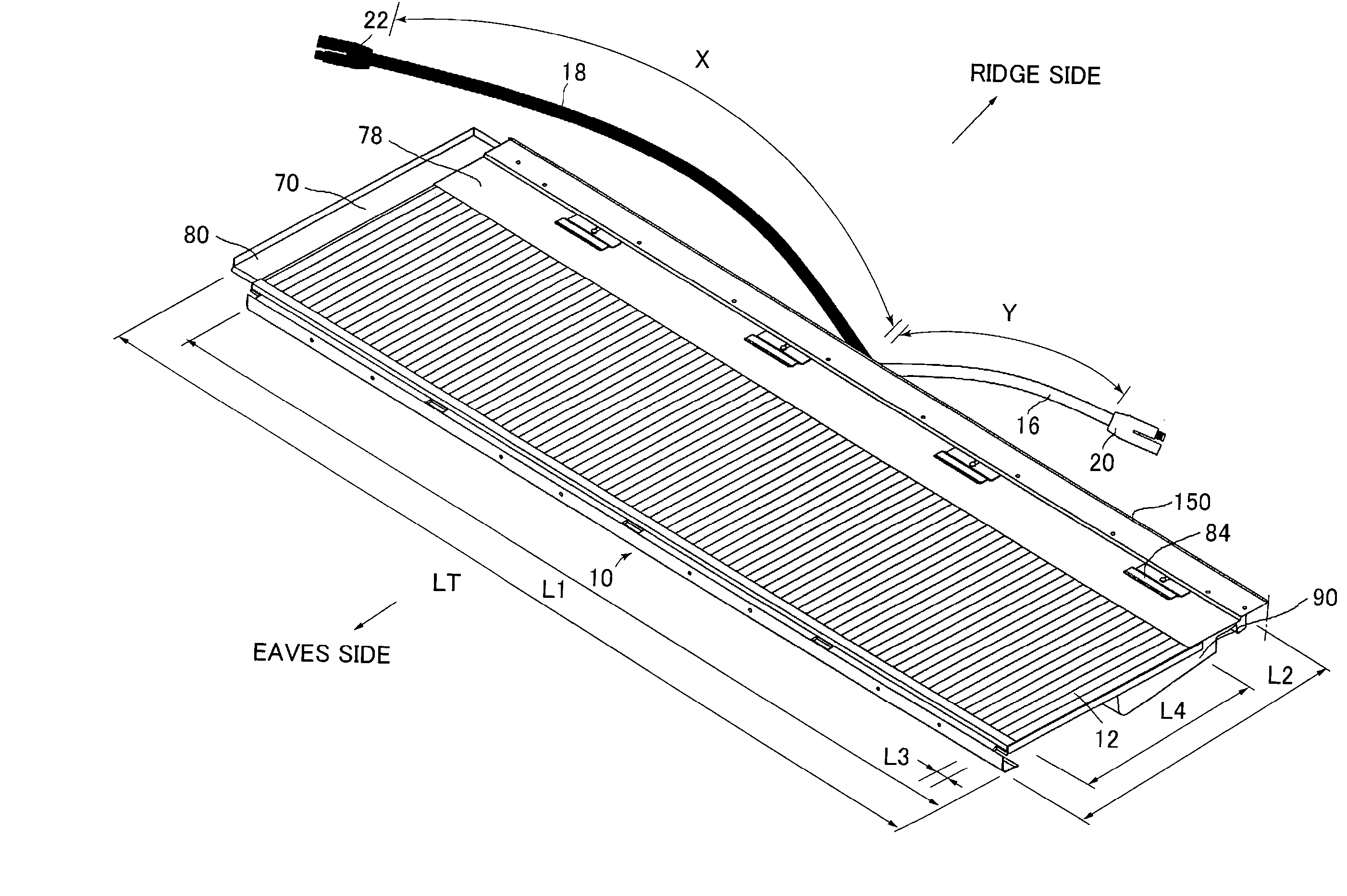
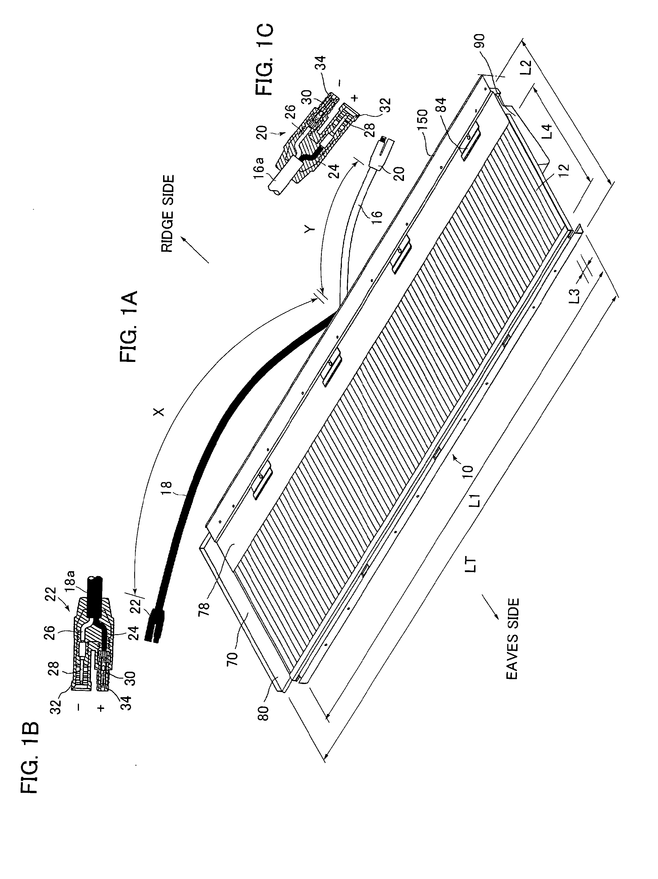
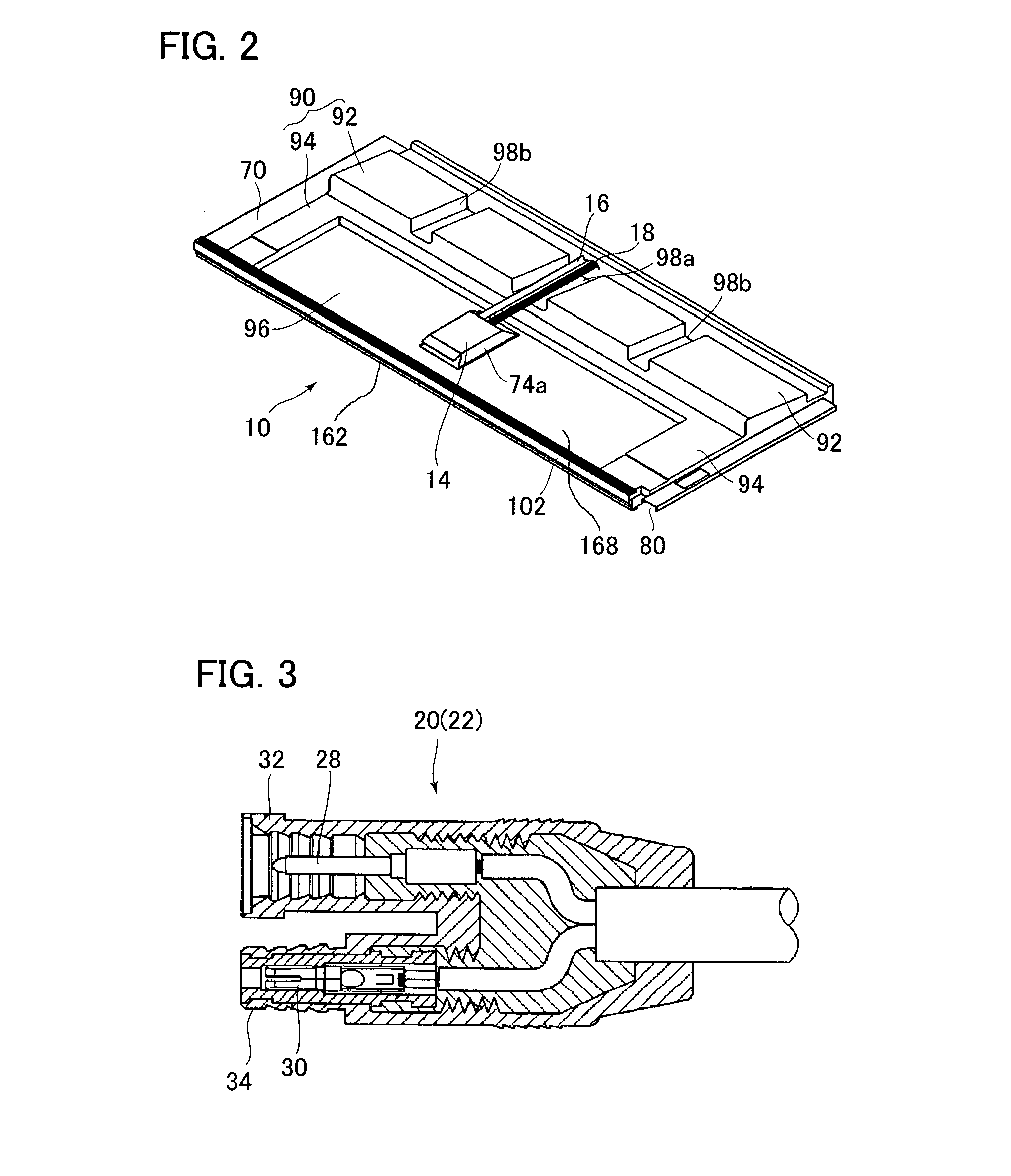
[0216]FIG. 1A is a perspective view of the roof-tile shaped solar cell module employed in the embodiment of the present invention. FIG. 4 is a cross section of the connector of the solar cell module shown in FIG. 1.

[0217]The roof-tile shaped solar cell module 10 is an integrated solar cell, in which a plurality of unit solar cells are formed so as to constitute a solar cell as a whole.

[0218]Specifically, the module 10 is formed by laminating a film such as a conducting film and a semiconductor film on a glass substrate, cutting a plurality of grooves on the laminated layer so that the layer is divided into a number of one-cell batteries (unit solar cells), and electrically connecting the unit solar cells in series.

[0219]The module 10 is of a rectangular shape as shown in figures with the two cables 16, 18 pulled out from a center part of its longer edge.

[0220]Further, the cables 16, 18 are connected to th...


PUM


Abstract

It is an object to provide a solar cell module having a uniform configuration, presenting stable output characteristics, and having a size enabling easy wiring in arrangement and a solar cell array presenting stable output characteristics by employment of said solar cell modules.A solar cell module 10 has a solar cell panel 12 having a length of its longer edges of 900 to 1100 mm. The solar cell panel 12 is constituted by a number of unit solar cells 100 connected in series and has an open-circuit voltage of 100 to 180 volts. The unit solar cell 100 is of a strip-like shape with a length of its shorter edges of 7 to 12 mm and arranged in a longer-edge direction of the panel 12 so that its longer edges extend in a shorter-edge direction of the panel 12 and its shorter edges extend in the longer-edge direction of the panel 12.

Description

TECHNICAL FIELD[0001]The present invention relates to a solar cell module for constituting a solar cell array arranged on a house and to a solar cell array constituted by the solar cell modules.BACKGROUND ART[0002]Recently, a photovoltaic system with solar cell modules having solar cell panels arranged on a place such as a roof of a house has increased for covering electricity consumed at the house and simultaneously selling surplus electricity to an electric power company. A solar cell panel is an integrated solar cell, which is formed by laminating a film such as a conducting film and a semiconductor film on a glass substrate, cutting a plurality of grooves on the laminated layer so as to form a predetermined number of one-cell batteries (unit solar cells), and electrically connecting the unit solar cells in series. It is known that some panels generate a voltage of 100 volts or more. The Patent Document 1 specified below discloses a method for manufacturing such a solar cell pane...

Claims


Application Information

Patent Timeline
Patent Type & Authority Applications(United States)
IPC IPC(8): E04D13/18
CPCH01L31/05Y02B10/12H02S40/34H02S40/36H02S20/23Y02E10/50Y02B10/10H01L31/0504
Inventor UEDA, YASUHIROYAMAWAKI, TAKEHARUISHIDA, KENSUKENAKAJIMA, TAKEHARUOBAYASHI, TADASHI
Owner KANEKA CORP
Learn More