Powder sprayer

Inactive Publication Date: 2011-07-07
KO CHUAN WEI
View PDF5 Cites 18 Cited by
  • Summary
  • Abstract
  • Description
  • Claims
  • Application Information

AI Technical Summary

Benefits of technology

[0005]The present invention has been accomplished under the circumstances in view. It is one object of the present invention to provide a powder sprayer, which uses a nozzle head and a nozzle tube for causing a venturi action to suck in a powder from a powder bottle for application. It is another object of the present invention to provide a powder sprayer, which ha

Problems solved by technology

However, when using a bottled perfume powder, it is difficult to control the applied amount of perfume powder.
This design of perfume powder spra

Method used


Image

  • Powder sprayer
  • Powder sprayer
  • Powder sprayer

Examples


Example

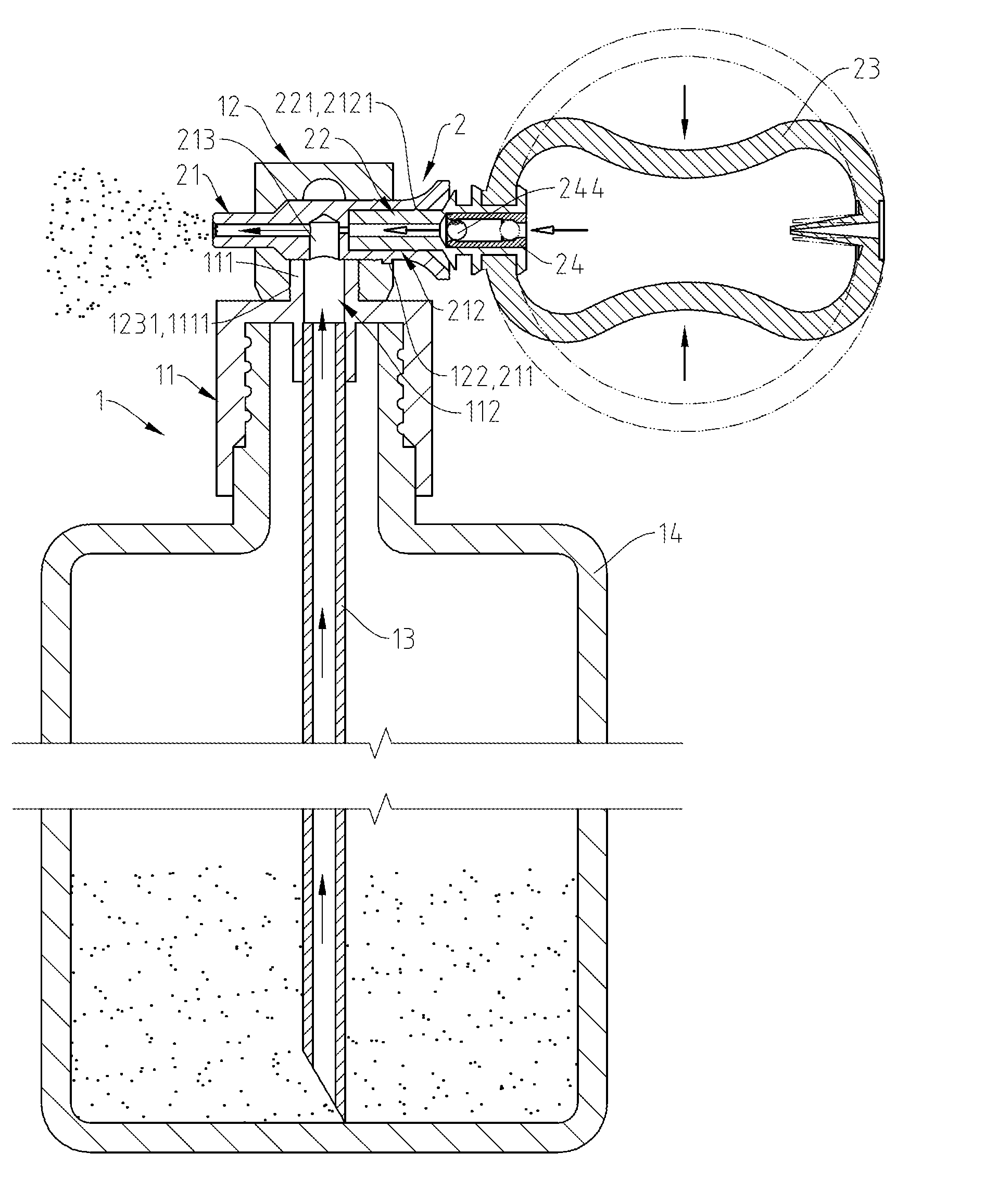
[0014]Referring to FIGS. 1-7, a powder sprayer in accordance with the present invention is shown comprising a sprayer body 1 and a spraying mechanism 2. The sprayer body 1 comprises a bottle cap 11, a nozzle head 12, a dip tube 13 and a powder bottle 14. The spraying mechanism 2 comprises a nozzle tube 21, a connection tube 22, an inflation bulb 23 and a valve tube 24.

[0015]The bottle cap 11 has a top neck 111, a first endless rib 1111 protruded from and extending around the periphery of the top neck 111 and a through hole 112 axially extending through the top neck 111.

[0016]The nozzle head 12 has a transverse mounting hole 121 transversely cut through the periphery thereof, a guide notch 122 located on the periphery at one end of the mounting hole 121, a bottom hole 123 located on the bottom side thereof, a first inside annular groove 1231 disposed inside the bottom hole 123 and a second inside annular groove 1211 disposed in one end of the mounting hole 121.

[0017]The nozzle tube 2...


PUM


Abstract

A powder sprayer includes a sprayer body having a nozzle head mounted on the top side of the bottle cap thereof, the nozzle head having a transverse mounting hole disposed in communication with a vertical through hole of the bottle cap and a guide notch located on the periphery at one end of the transverse mounting hole, and a spraying mechanism having a nozzle tube positioned in the transverse mounting hole, the nozzle tube having a guide block protruded from the periphery thereof and fitting the guide notch of the nozzle head, an axial air passage and a transverse suction hole disposed in communication between the air passage and the through hole of the bottle cap for sucking powder from the powder bottle through a dip tube into the air passage upon passing of a flow of forced air through the air passage.

Description

BACKGROUND OF THE INVENTION[0001]1. Field of the Invention[0002]The present invention relates to sprayers and more particularly, to a powder sprayer, which has a simple structural design.[0003]2. Description of the Related Art[0004]Perfume powder for hair, face or body application may be contained in a bottle or spray bottle. However, when using a bottled perfume powder, it is difficult to control the applied amount of perfume powder. The most commonly used design of perfume powder sprayer comprises a powder bottle, an accumulator fastened to the top side of the powder bottle and holding a dip tube in the powder bottle, a nozzle tube fastened to the accumulator at one side and an inflation bulb connected to the accumulator at the opposite side. When the user compresses the inflation bulb to force the inside air out of the inflation bulb through the accumulator and the nozzle tube, a vacuum suction force is produced in the accumulator subject to a venturi action, causing the dip tube...

Claims


Application Information

Patent Timeline
IPC IPC(8): B05B9/03
CPCB05B11/062B05B11/06
Inventor KO, CHUAN-WEI
Owner KO CHUAN WEI
Why Eureka
Try Eureka