
Light output device and assembly method

a technology of light output device and assembly method, which is applied in the direction of semiconductor devices for light sources, lighting and heating apparatus, and light support devices, etc., can solve problems such as design constraints, and achieve the effect of improving the light output devi

Inactive Publication Date: 2011-07-07
KONINKLIJKE PHILIPS ELECTRONICS NV
View PDF5 Cites 18 Cited by
  • Summary
  • Abstract
  • Description
  • Claims
  • Application Information

AI Technical Summary

Benefits of technology

[0005]It is an object of the present invention to at least partly overcome this drawback, and to provide an improved light output device.
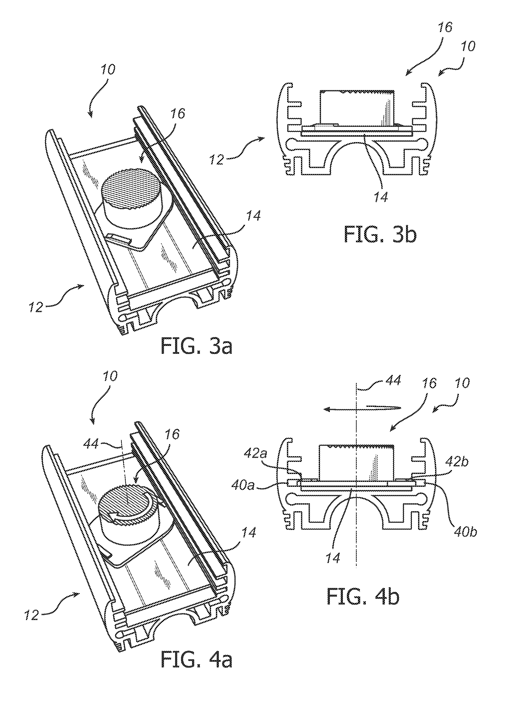
[0008]A bayonet type mechanism may generally be defined as an arrangement for fastening with a short rotational movement two connecting parts of rotary symmetrical character to each other. By using a bayonet type mechanism, simply twisting the optical component may fixate the optical component in the right position and also fixate the substrate to the heat sink. The latter ensures thermal contact between the substrate and the heat sink. Fixation of the substrate to the heat sink is thus advantageously carried out without having to use flexible elements, or screws, glue or other additional components. Also, the substrate may be forced to the heat sink where it is needed: namely around the at least one LED.
[0010]Preferably, the substrate is a printed circuit board, the optical component is a collimating lens, and the at least one light emitting element is at least one light emitting diode (chip or package). Benefits of LEDs include high efficiency, long useful life, etc. Alternative substrates include, but are not limited to, a wired circuit board. Alternative optical components include, but are not limited to, a protective transparent or translucent cover, a diffusing cover, a lens, a reflector, etc. Alternative light emitting elements include, but are not limited to, organic light emitting diodes (OLEDs), laser diodes, etc.

Problems solved by technology

A drawback with the solution presented in Matheson is that the flexible property of the housing element imposes design constraints on the housing element with respect to material and shape selection.

Method used


Image

  • Light output device and assembly method
  • Light output device and assembly method
  • Light output device and assembly method

Examples


Embodiment Construction

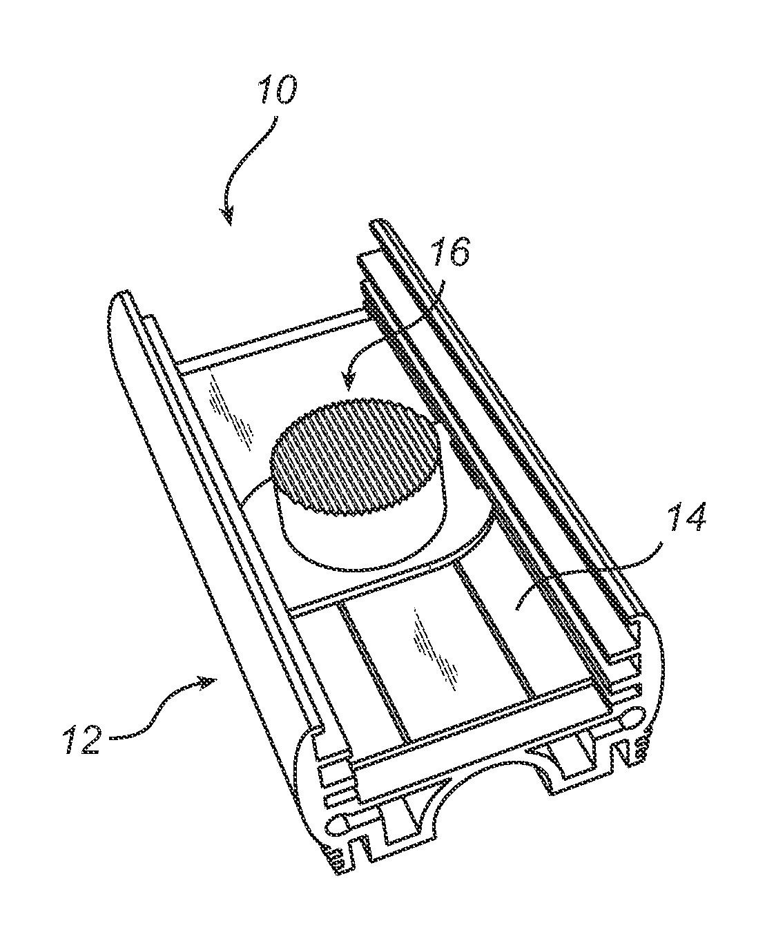
[0015]A light output device 10 according to an embodiment of the present invention will now be described with reference to the appended drawings.

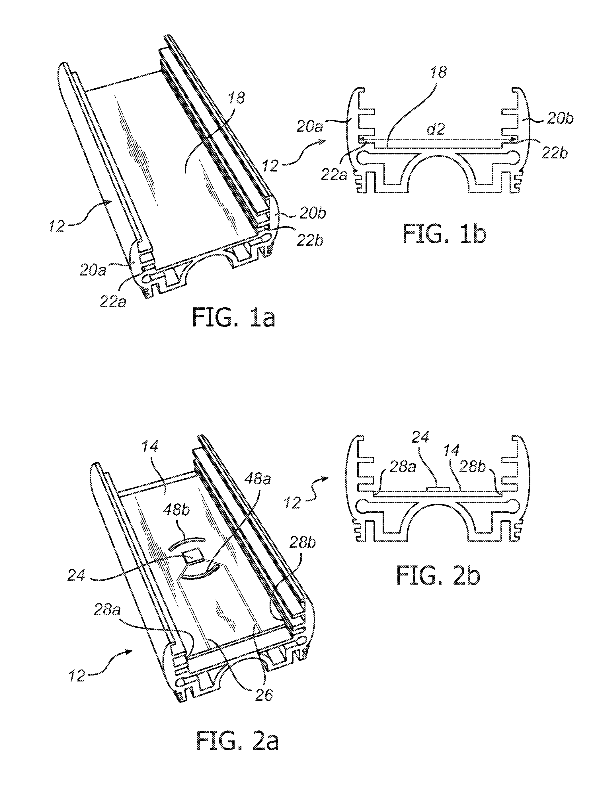
[0016]The light output device 10 comprises a heat sink 12, a PCB 14, and an optical component 16.

[0017]The heat sink 12 is preferably made of a material with high thermal conductivity, such as metal, in particular aluminum. The present heat sink 12 is a profiled channel having a base portion 18 and two side wall portions 20a, 20b. Two opposite grooves 22a, 22b run along the inside of the wall portion 20a, 20b near the base portion 18, as illustrated in e.g. FIGS. 1a-1b. The heat sink 12 may optionally comprise a plurality of fins for enhanced heat dissipation.

[0018]The PCB 14 comprises at least one LED 24 thermally connected thereto. The LED 24 may be an LED package, or a chip or die mounted directly on the PCB 14. The PCB 14 further comprises electrically conductive traces 26 or the like for electrically connecting the LED(s) 24 to a power...


PUM


Abstract

The present invention relates to a light output device (10) comprising a heat sink (12); a substrate (14) with at least one light emitting element (24) arranged thereon; and an optical component (16), wherein the optical component is mounted to the heat sink by means of a bayonet type mechanism, and wherein the substrate is fixed between the heat sink and the optical component. The present invention also relates to a method of assembling such a light output device.

Description

FIELD OF THE INVENTION[0001]The present invention relates to a light output device, in particular a light output device comprising at least one light emitting diode (LED), as well as a method of assembling such a light output device.BACKGROUND OF THE INVENTION[0002]Generally, printed circuit boards (PCBs) with LEDs are often glued, screwed or clamped to a heat sink to ensure thermal contact and sufficient heat conduction away from the LEDs. Also, often optics are placed over the LEDs to provide a desired radiation pattern or to protect the LED.[0003]U.S. Pat. No. 7,348,604 (Matheson) discloses a light-emitting module comprising heat dissipation element, a substrate coupled to one or more light emitting elements, and a housing element including fastening means for coupling the housing element to the heat dissipation element, the substrate allegedly being enclosed between the heat dissipation element and the housing element. The housing element is provided with an optical element, and...

Claims


Application Information

Patent Timeline
Patent Type & Authority Applications(United States)
IPC IPC(8): H01L33/58
CPCF21K9/00F21S4/003F21V5/04F21V7/0091F21V29/74F21V21/34F21V29/004F21Y2101/02F21V17/14F21S4/20F21Y2115/10F21V29/70F21V29/00
Inventor VAN ELMPT, ROB FRANCISCUS MARIASIPKES, MARK EDUARD JOHAN
Owner KONINKLIJKE PHILIPS ELECTRONICS NV
Learn More