Image source unit and display device including the same

a technology of image source and display device, which is applied in the manufacture of electric discharge tubes/lamps, lighting and heating apparatuses, instruments, etc., can solve the problems of not controlling the angle of light incident on and the amount of image light that is absorbed by the light absorbing portion is not small, so as to achieve efficient reflection and improve the use efficiency of image light

Active Publication Date: 2011-07-07
DAI NIPPON PRINTING CO LTD
View PDF6 Cites 14 Cited by
  • Summary
  • Abstract
  • Description
  • Claims
  • Application Information

AI Technical Summary

Benefits of technology

[0023]According to the invention, the image light can be efficiently reflected from the image source and provided to the observer side. Accordingly use efficiency of the image light can be improved.

Problems solved by technology

However, in the example that is disclosed in JP-A No. 2003-66206, an incident angle of light that is incident on the light absorbing portions is not controlled and the amount of image light that is absorbed by the light absorbing portions is not small.

Method used


Image

  • Image source unit and display device including the same
  • Image source unit and display device including the same
  • Image source unit and display device including the same

Examples


example

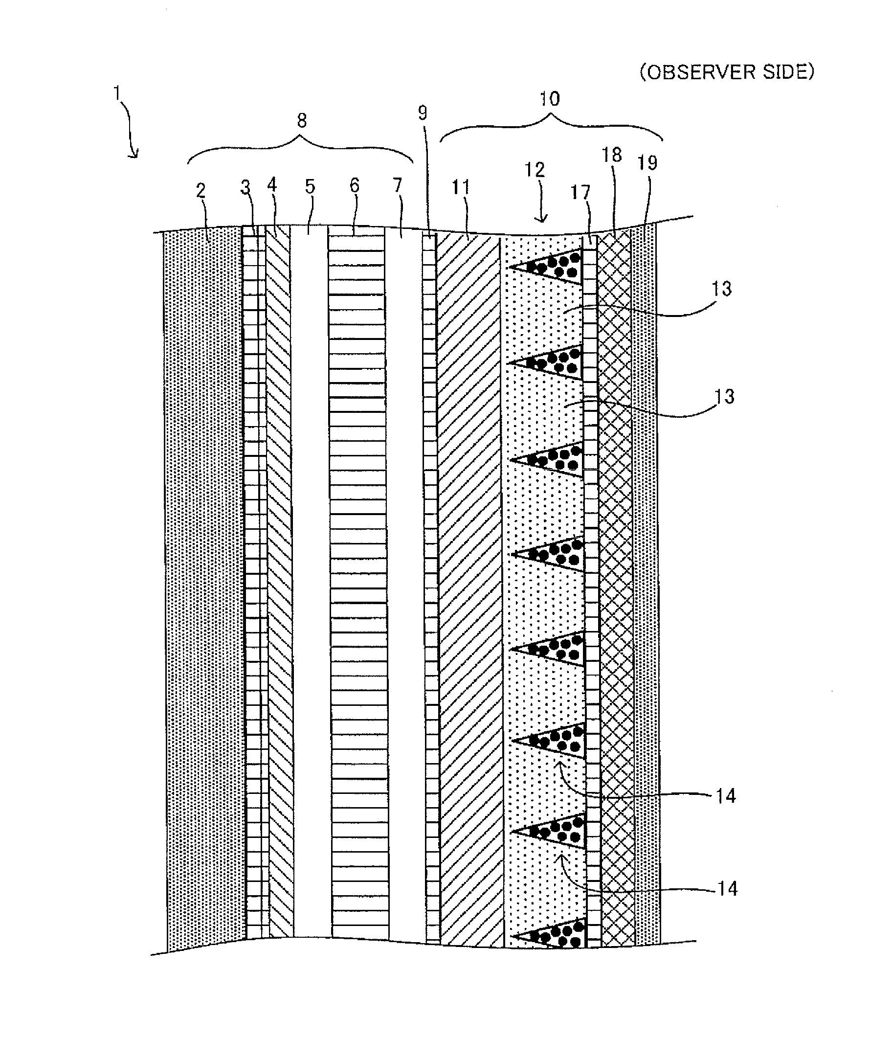
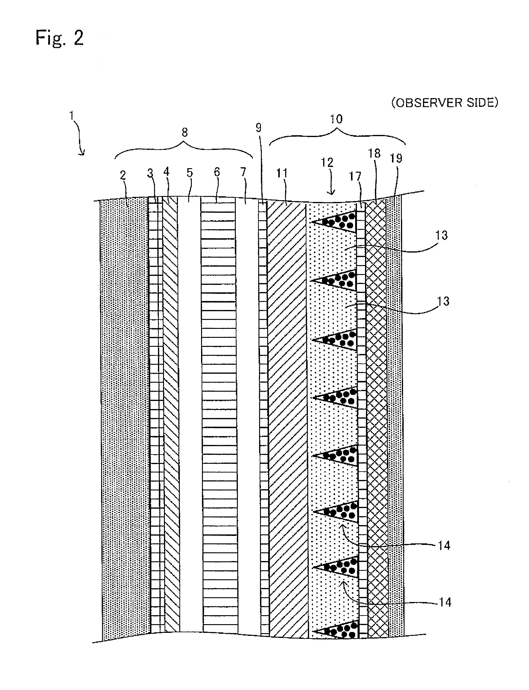
[0182]As the example, the image source unit that has the layer structure shown in FIG. 2 is formed. With changing the conditions of the above equation 5, that is, with changing the refractive index θb of the optical functional layer and the half-value angle θ0 of the divergence angle, the light transmission efficiency at each condition is investigated. As the backlight (2), the cold cathode fluorescent lamp (CCFL) is used. As the optical control sheet (4), the sheet providing the light-transmitting portions arranged along the sheet surface is used, wherein the light-transmitting portions have the cross section of the trapezoidal shape in which the shorter upper base is the light source side and the longer lower base is the observer side. Between the light-transmitting portions of the optical control sheet (4), the low refractive-index portions having the cross section of the triangular shape are disposed, wherein the refractive index of the low refractive-index portions is lower tha...


PUM

PropertyMeasurementUnit
particle sizeaaaaaaaaaa
angleaaaaaaaaaa
angleaaaaaaaaaa

Abstract

An image source unit that can efficiently provide image light emitted from an image source to an observer is disclosed. The image source unit includes an image source; and an optical sheet that disposed closer to an observer side than the image source. The optical sheet includes an optical functional layer that includes a light-transmitting portion having a trapezoidal cross section; and the low refractive-index portion having a wedge shape cross section. An oblique side of the wedge shape cross section of the low refractive-index portion form an angle of θb with respect to a normal line of the sheet surface.

Description

BACKGROUND OF THE INVENTION[0001]1. Field of the Invention[0002]The present invention relates to a display device such as a liquid crystal television and an image source unit that is used in the display device. More particularly, the invention relates to a display device and an image source unit that can efficiently emit light from an image source.[0003]2. Description of the Related Art[0004]A display device such as a liquid crystal television comprises an image source such as a liquid crystal panel that outputs an image to be displayed and an optical sheet that improves a quality of image light emitted from the image source and transmits the image light to an observer side. In order to provide a higher quality image to an observer, the optical sheet is generally configured by stacking layers having various functions.[0005]An example of the conventional optical sheet is disclosed in Japanese Patent Application Laid-Open (JP-A) No. 2003-66206. According to this example, the optical s...

Claims


Application Information

Patent Timeline
Patent Type & Authority Applications(United States)
IPC IPC(8): G02F1/1335G02B1/11H01J9/20
CPCG02B5/0231G02F2001/133562G02F1/133504G02F1/133562
Inventor KASHIWAGI, TSUYOSHI
Owner DAI NIPPON PRINTING CO LTD
Why Eureka
Try Eureka