Display device

a display device and display panel technology, applied in the field of display devices, can solve the problems of poor production efficiency and difficulty in fabricating /4 plates, and achieve the effects of reducing the components of light reflected upon entering the display device, and reducing the absolute quality of ligh

Active Publication Date: 2011-07-07
SHARP KK
View PDF7 Cites 22 Cited by
  • Summary
  • Abstract
  • Description
  • Claims
  • Application Information

AI Technical Summary

Benefits of technology

[0012]With the foregoing in view, it is an object of the present invention to provide a display device which can reduce reflected light reflected on the respective surfaces of a display panel and a protective plate without employing a complicated structure and without degrading display quality, even if the protective plate is disposed on the surface of the display panel.

Problems solved by technology

And it has been discovered that according to the conventional structure, an antireflection effect can be obtained by the structure of the circularly polarizing plate, but a new λ / 4 plate must be fabricated and in particular the λ / 4 plate must be attached such that the optical axis (stretch axis) is turned 45° from the polarization axis of the polarizer, this is however a branch type attachment of which production efficiency is poor, and it is actually difficult to fabricate a λ / 4 plate which provides a phase difference of one fourth of the wavelength λ without error, or which has an optical axis in a desired direction by specifying the stretch axis direction without error.

Method used


Image

  • Display device
  • Display device
  • Display device

Examples


embodiment 1

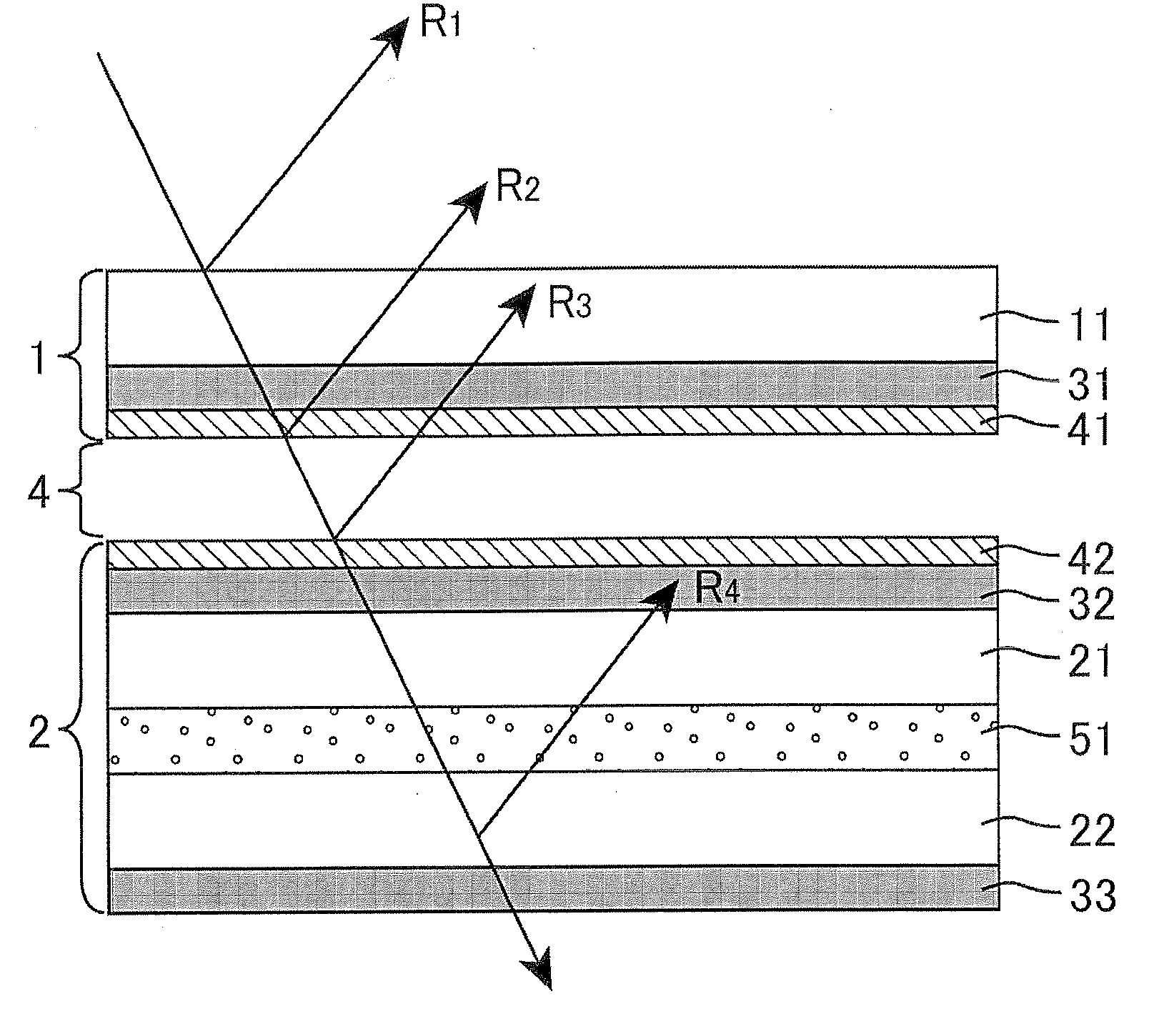
[0047]FIG. 1 is a cross-sectional view schematically depicting a configuration of a display device of Embodiment 1. The display device of Embodiment 1 has a display panel 2 and a protective plate 1 disposed facing the display panel 2, and the display panel 2 and the protective plate 1 are disposed in this order toward the display surface side (observation surface side). By disposing the protective plate 1 on the display surface side of the display panel 2, scratches and contamination of the display panel 2 can be prevented, and the display panel 2 can be protected from impact from the outside. The protective plate 1 includes a protective base material 11 and a first polarizer 31, and the protective base material 11 mainly serves as the protective plate 1. The material of the protective base material 11 is not particularly limited, but is preferably transparent and is rigid under normal temperatures. Examples of such a material include glass and curable resin having transparency. The...

embodiment 2

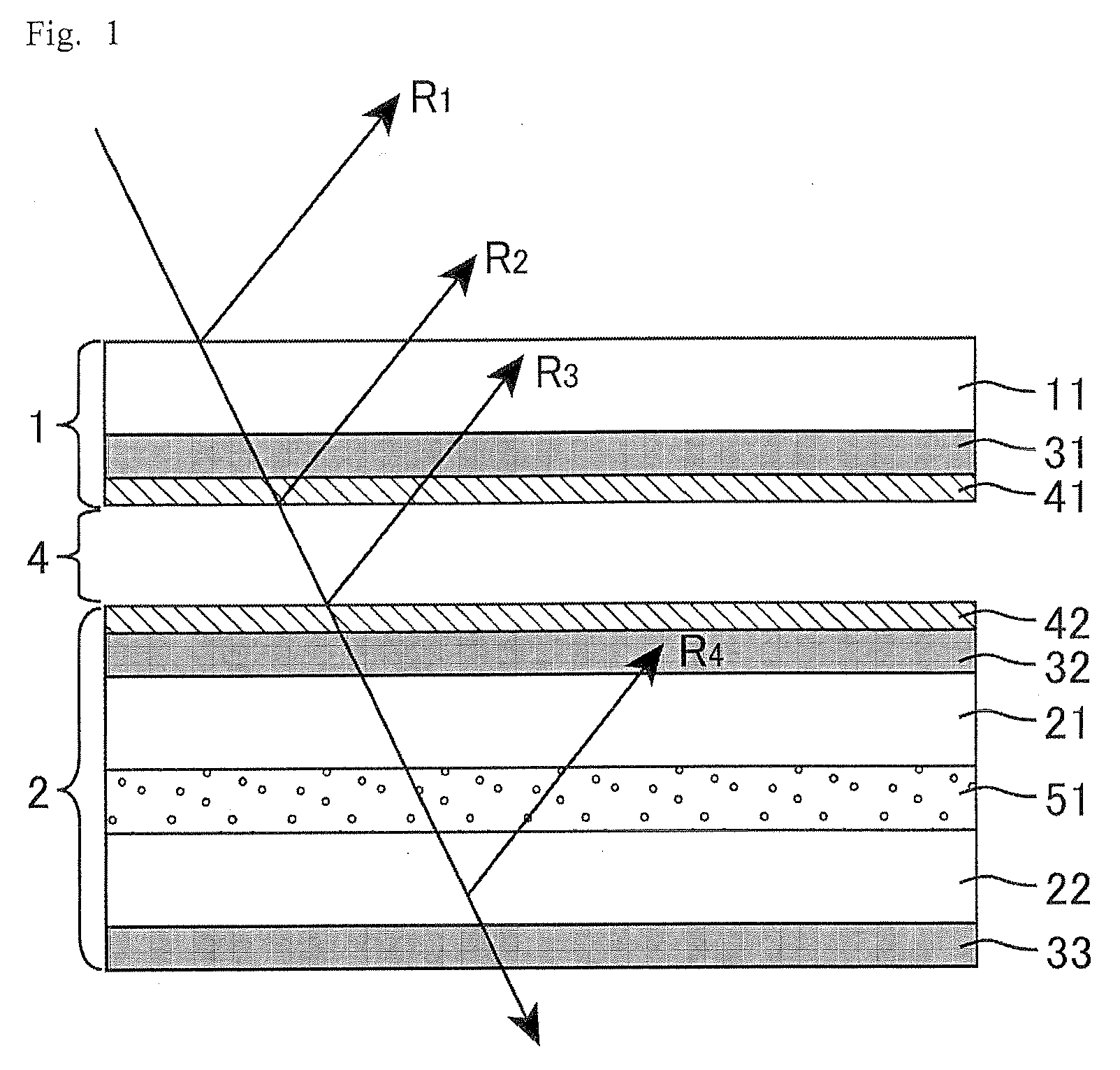
[0066]FIG. 2 is a cross-sectional view schematically depicting a configuration of a display device of Embodiment 2. The display device of Embodiment 2 is the same as the display device of Embodiment 1, except that the antireflection layer is not disposed on the display panel side surface of the protective plate or on the protective plate side surface of the display panel.

[0067]The path of light when the incident light into the liquid crystal display device of Embodiment 2 is reflected, and reflectance at each reflection point will be described with reference to FIG. 2.

[0068]A part of the components of the light entered from the outside is reflected on the surface of the protective plate 1 facing the outside, and emitted to the outside as reflected light R1. If the protective base material 11 is made of glass, the reflectance here is about 4.0%. Therefore if the intensity of the incident light is 100%, the intensity of the reflected light R1, which is emitted to the outside, is 4.0%....

embodiment 3

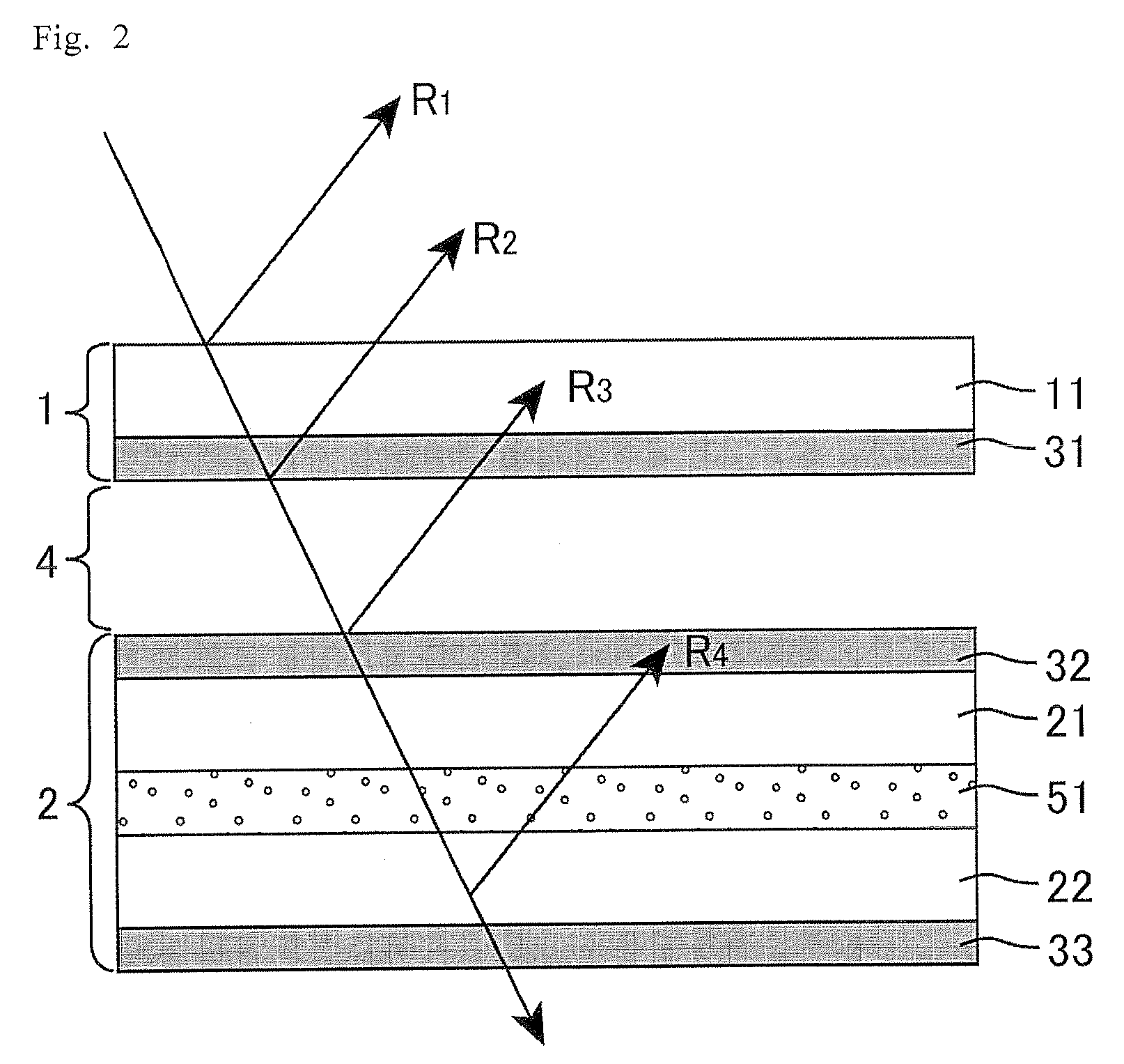
[0074]FIG. 3 is a cross-sectional view schematically depicting a configuration of a display device of Embodiment 3. The display device of Embodiment 3 is the same as the display device of Embodiment 1, except that the antireflection layer is disposed only on one of the surface of the protective plate and the surface of the display panel. In FIG. 3, a first antireflection layer 41 is on the display panel 2 side surface of the protective plate 1, but a same effect can be obtained even in a configuration where a second antireflection layer is on the protective plate 1 side surface of the display panel 2, and this configuration is also included in the present embodiment.

[0075]The path of light when the light entered the liquid crystal display device of Embodiment 3 is reflected, and reflectance at each reflection point will be described with reference to FIG. 3.

[0076]A part of the components of the light entered from the outside are reflected on the surface of the protective plate 1 fac...


PUM

PropertyMeasurementUnit
angleaaaaaaaaaa
transmittanceaaaaaaaaaa
center wavelengthaaaaaaaaaa

Abstract

The present invention provides a display device which can reduce reflected light reflected on the respective surfaces of a display panel and a protective plate, even if the protective plate is disposed on the surface of the display panel, without employing a complicated structure and without degrading display quality. The display device includes: a display panel; and a protective plate disposed facing the display panel. The protective plate has a protective base material and a first polarizer, the display panel has a second polarizer of which a polarization axis is parallel to that of the first polarizer, and light passing between the first polarizer and the second polarizer is linearly polarized light.

Description

TECHNICAL FIELD[0001]The present invention relates to a display device, and more particularly to a display device in which a protective plate for protecting a display panel is provided for the display panel.BACKGROUND ART[0002]For a surface of a display panel, such as a cathode ray tube (CRT) display panel, liquid crystal display (LCD) panel, plasma display panel (PDP) and electro-luminescence (EL) display panel, various functions, including a scratch prevention function and a contamination prevention function, are required. Liquid crystal alignment defects may be generated when, for example, the liquid crystal display panel is subjected to an external impacts. Therefore in order to prevent scratches and contamination, and protect from an external impact, in some cases a protective plate is disposed on the surface of the display panel.[0003]If such a protective plate is disposed on the surface of the display panel, light is reflected not only on the surface of the liquid crystal dis...

Claims


Application Information

Patent Timeline
Patent Type & Authority Applications(United States)
IPC IPC(8): G02F1/1335G02B5/30G02B1/11H01J1/62
CPCG02B27/0018G02B27/28H01L51/5281H01L51/5237G02F2201/50H10K50/841H10K50/86
Inventor TSUDA, KAZUHIKO
Owner SHARP KK
Why Eureka
Try Eureka