Plant for forming electronic circuits on substrates

a technology of electronic circuits and substrates, applied in the direction of liquid surface applicators, coatings, chemical vapor deposition coatings, etc., can solve the problems of reducing the throughput of substrates, limiting production capacity, and longer production times, so as to reduce the processing time of each individual substrate, the production capacity of cluster tools, and the effect of increasing the speed

Inactive Publication Date: 2011-07-07
APPLIED MATERIALS ITALIA SRL
View PDF6 Cites 15 Cited by
  • Summary
  • Abstract
  • Description
  • Claims
  • Application Information

AI Technical Summary

Benefits of technology

[0011]According to an advantageous feature of the present invention, the cluster tool comprises a plurality of production stations that are disposed along said closed circuit. The use of a closed circuit along which numerous transport elements move, and the presence of a plurality of production stations along the same circuit, allow to processing of several substrates at the same time and in parallel. This configuration is believed to provide greater production capacity of the cluster tool. According to a characteristic feature of the present invention, the movement means define a substantially closed circuit, along which a plurality of transport elements are able to be moved, and on each of which at least one of the substrates is disposed. The number of production stations that can be positioned along the same closed circuit depends on the production capacity which is needed, therefore the cluster tool according to the present invention is modular and is therefore can be configured to meet different production capacity requirements.
[0012]Advantageously the movement means comprise at least an electromagnetic guide, along which a plurality of transport elements are able to move at a higher speed than that of a conventional conveyor belt. This allows the processing times of each individual substrate to be reduced. According to another advantageous feature of the present invention, each transport element also comprises a drive member to actuate the movement of each transport element.

Problems solved by technology

One disadvantage of these known types of cluster tools is that the individual and sequential feed of the substrates causes a reduction in the substrate throughput, in particular in correspondence with the work stations that have a longer processing times, such as for example the metal deposition stations.
This limits the production capacity of the cluster tool and causes longer production times and therefore higher energy consumption and increased production cost.
Moreover these conventional cluster tools only generally contain a substrate identification device, which is disposed in a storage station contained within the cluster tool.

Method used


Image

  • Plant for forming electronic circuits on substrates
  • Plant for forming electronic circuits on substrates
  • Plant for forming electronic circuits on substrates

Examples


Embodiment Construction

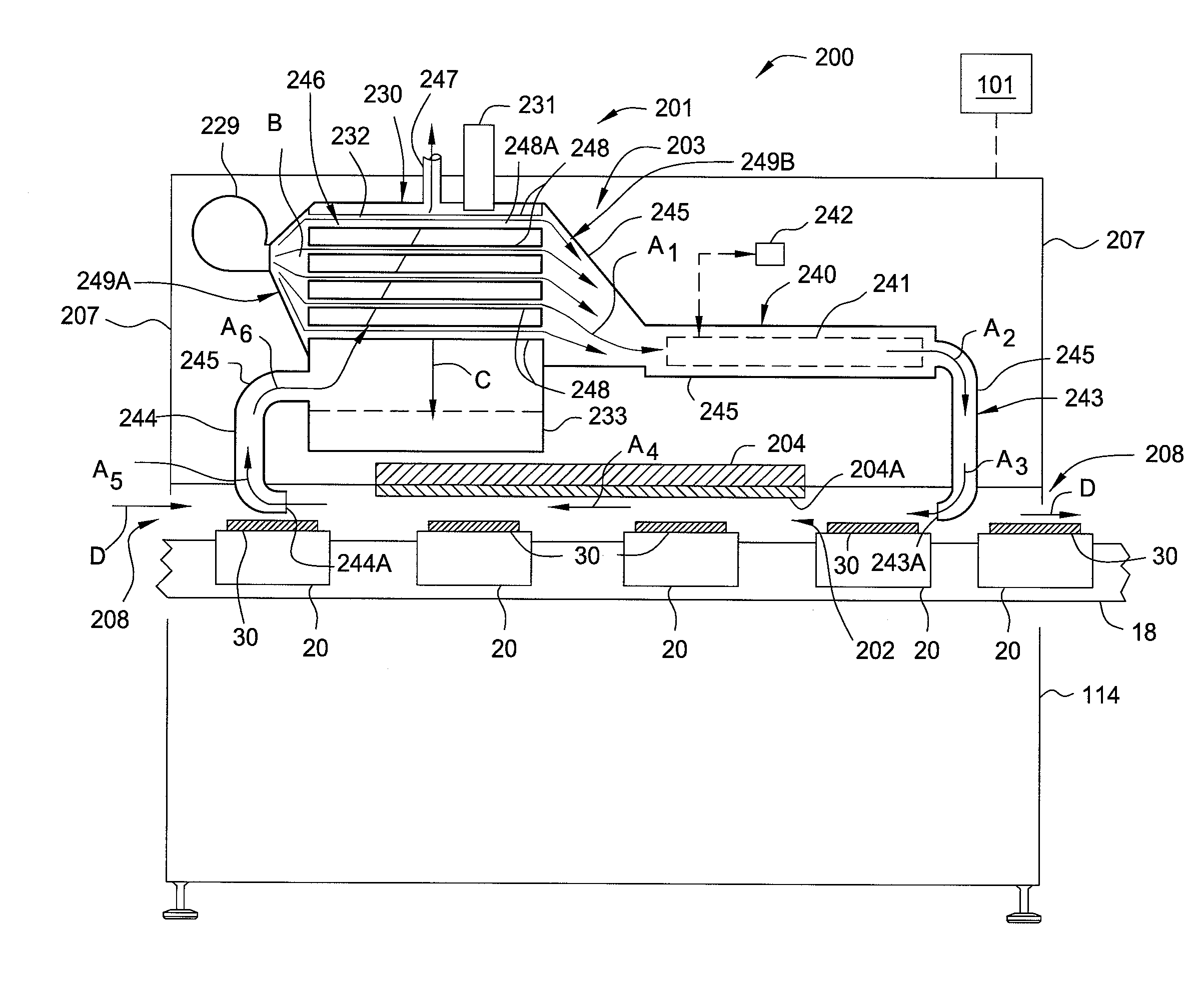
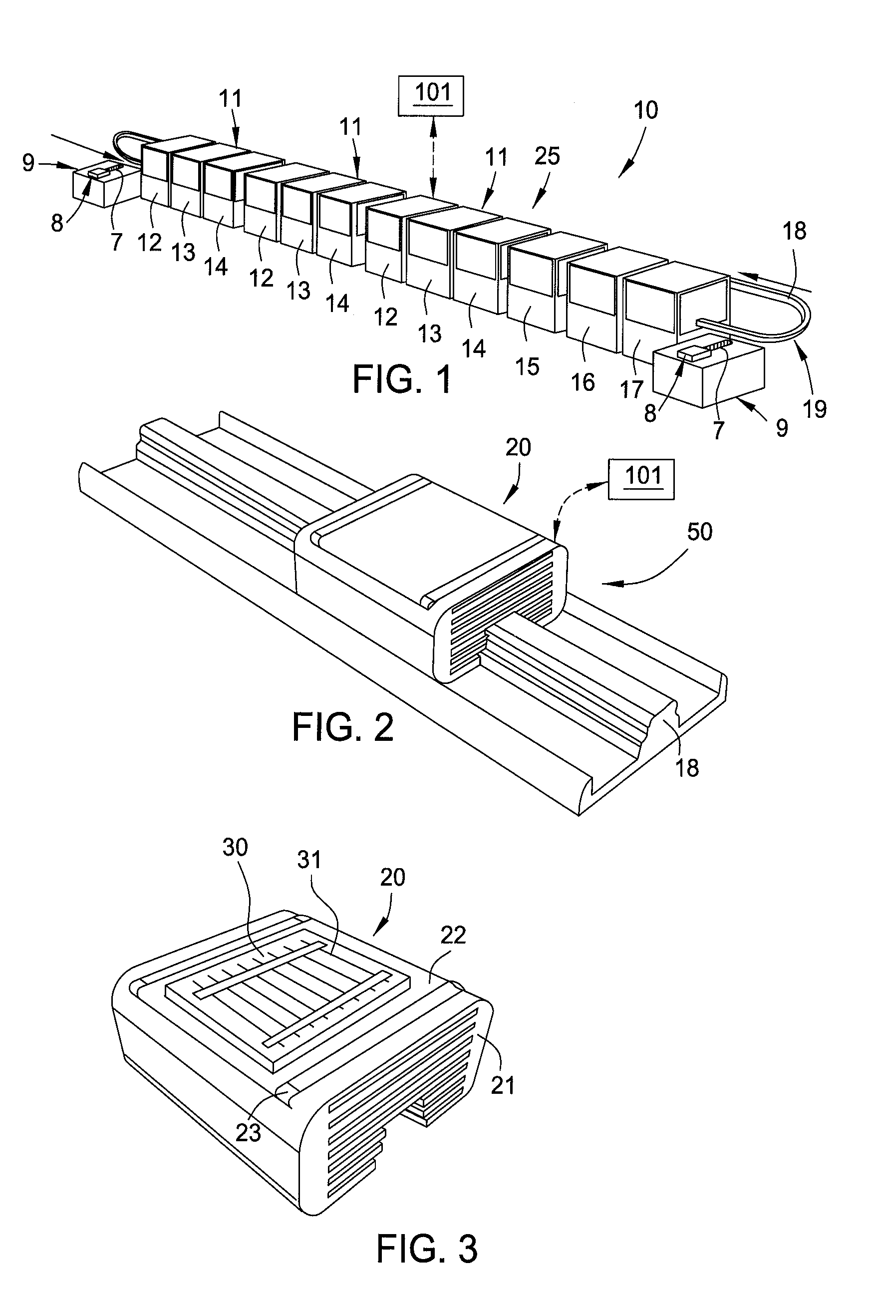
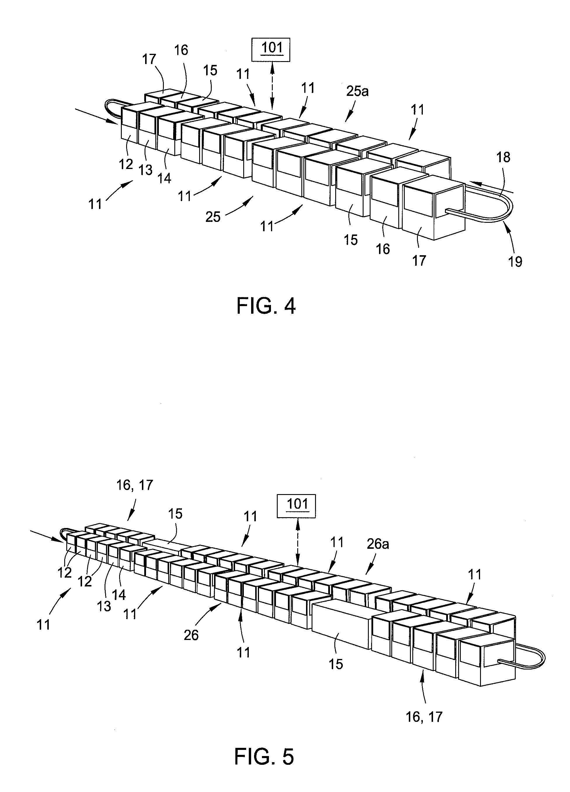
[0024]Embodiments of the present invention generally provide a cluster tool 10 that can be used to form electronic circuits on a substrate in an automated fashion. In one embodiment, the cluster tool 10 is adapted to process portions of a substrate to form part of a photovoltaic cell or a green-tape type circuit device in an automated fashion using a system controller 101. In one embodiment, as shown in FIG. 1, the cluster tool 10 comprises a work station 11, which comprises a deposition station 12 that can be used to deposit a metal or dielectric layer on a substrate.

[0025]In one embodiment, the deposition station 12 comprises a screen print chamber that is adapted to deposit a material in a desired pattern on the surface of the substrate. An exemplary screen printing chamber that may be adapted to deposit a material layer on a surface of a substrate disposed on a transport shuttle 20 (discussed below) is further described in the commonly assigned U.S. patent application Ser. No. 1...


PUM

PropertyMeasurementUnit
temperatureaaaaaaaaaa

Abstract

Embodiments of the present invention generally provide a cluster tool 10 that can be used to form electronic circuits on a substrate in an automated fashion. In one embodiment, the cluster tool 10 is adapted to process portions of a substrate to form part of a photovoltaic cell or a green-tape type circuit device in an automated fashion using a system controller 101. In one embodiment, the cluster tool 10 having plurality of work stations that comprise at least one station to deposit a layer on a substrate, a drying oven to dry the substrates, a testing station to test the substrates, and a storage station to store the substrates, and a transport element that is positionable in each of the work stations. A guide defines a substantially closed circuit along which a plurality of transport elements are able to be moved, on each of which at least one of the substrates is disposed.

Description

BACKGROUND OF THE INVENTION[0001]1. Field of the Invention[0002]The present invention concerns a cluster tool used to form electronic circuits, having a defined geometric shape on a substrate formed from, for example, a material such as silicon or alumina. In particular the cluster tool, comprising a plurality of work stations associated and coordinated with each other, is preferably but not restrictively used to make photovoltaic cells and green-tape type circuits.[0003]2. Description of the Background Art[0004]Cluster tools having a plurality of work stations that are used to process and / or form electronic circuits on a substrate, such as silicon or alumina, are known. In particular such work stations comprise at least a station for loading the substrates, a station that is able to deposit a metal layer on a substrate, at least an oven in which the metalized substrates are subjected to a drying process, at least one testing station to carry out a qualitative test on the substrates...

Claims


Application Information

Patent Timeline
Patent Type & Authority Applications(United States)
IPC IPC(8): B05D3/00B05C11/00B05C9/12B05D3/06
CPCH01L21/67017H01L21/6776H01L21/67721H01L21/67173C23C16/4418C23C16/54H01L21/67132H01L21/67144
Inventor BACCINI, ANDREA
Owner APPLIED MATERIALS ITALIA SRL
Why Eureka
Try Eureka