
Systems and methods for finite element based topology optimization

a finite element and optimization technology, applied in multi-objective optimization, instruments, cad techniques, etc., can solve the problems of numerical procedures becoming necessary, failure to provide optimal topology, and inability to determine analytically optimal topology

Inactive Publication Date: 2011-07-07
BOARD OF GOVERNORS FOR HIGHER EDUCATION STATE OF RHODE ISLAND & PROVIDENCE PLANTATIONS
View PDF0 Cites 20 Cited by
  • Summary
  • Abstract
  • Description
  • Claims
  • Application Information

AI Technical Summary

Benefits of technology

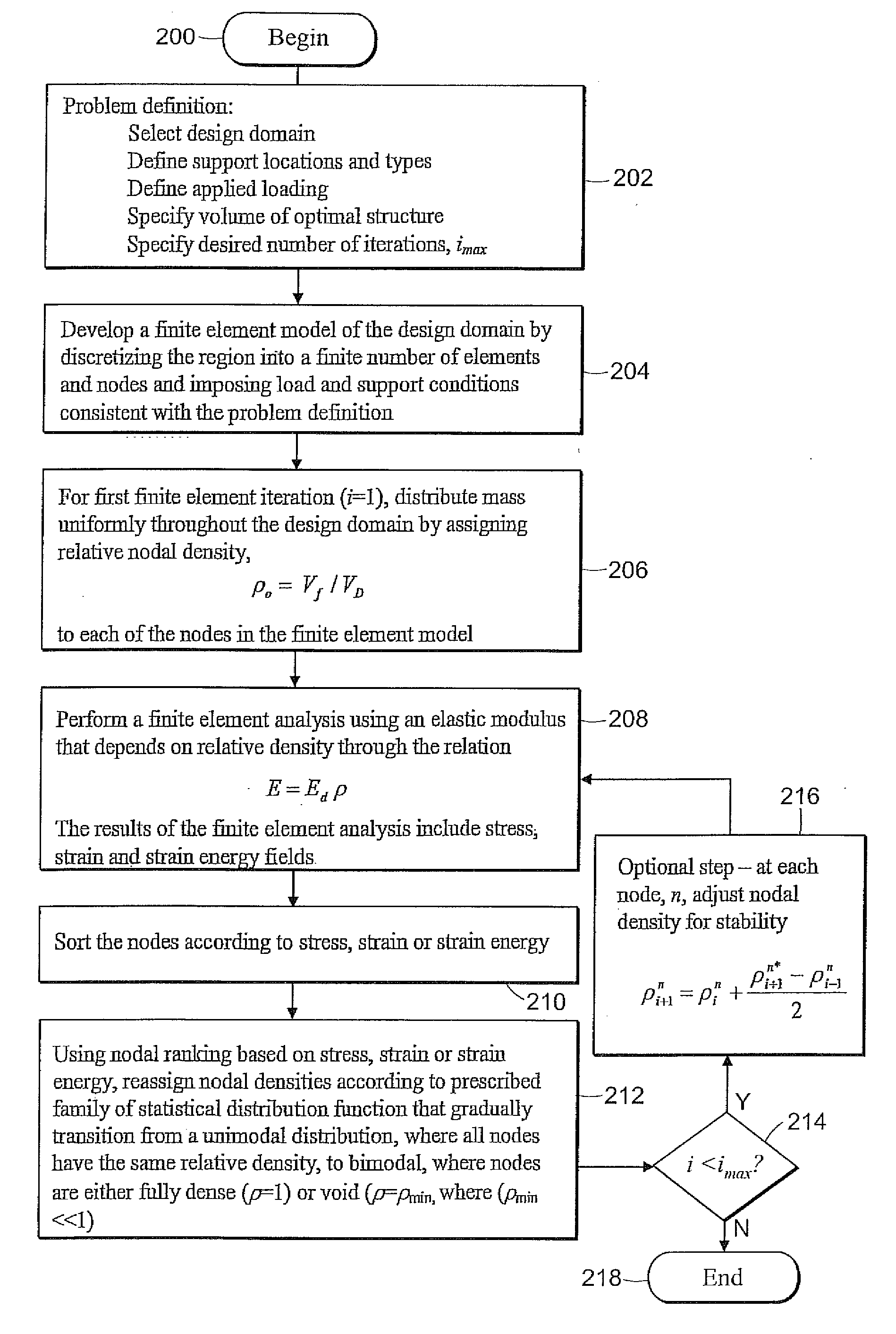
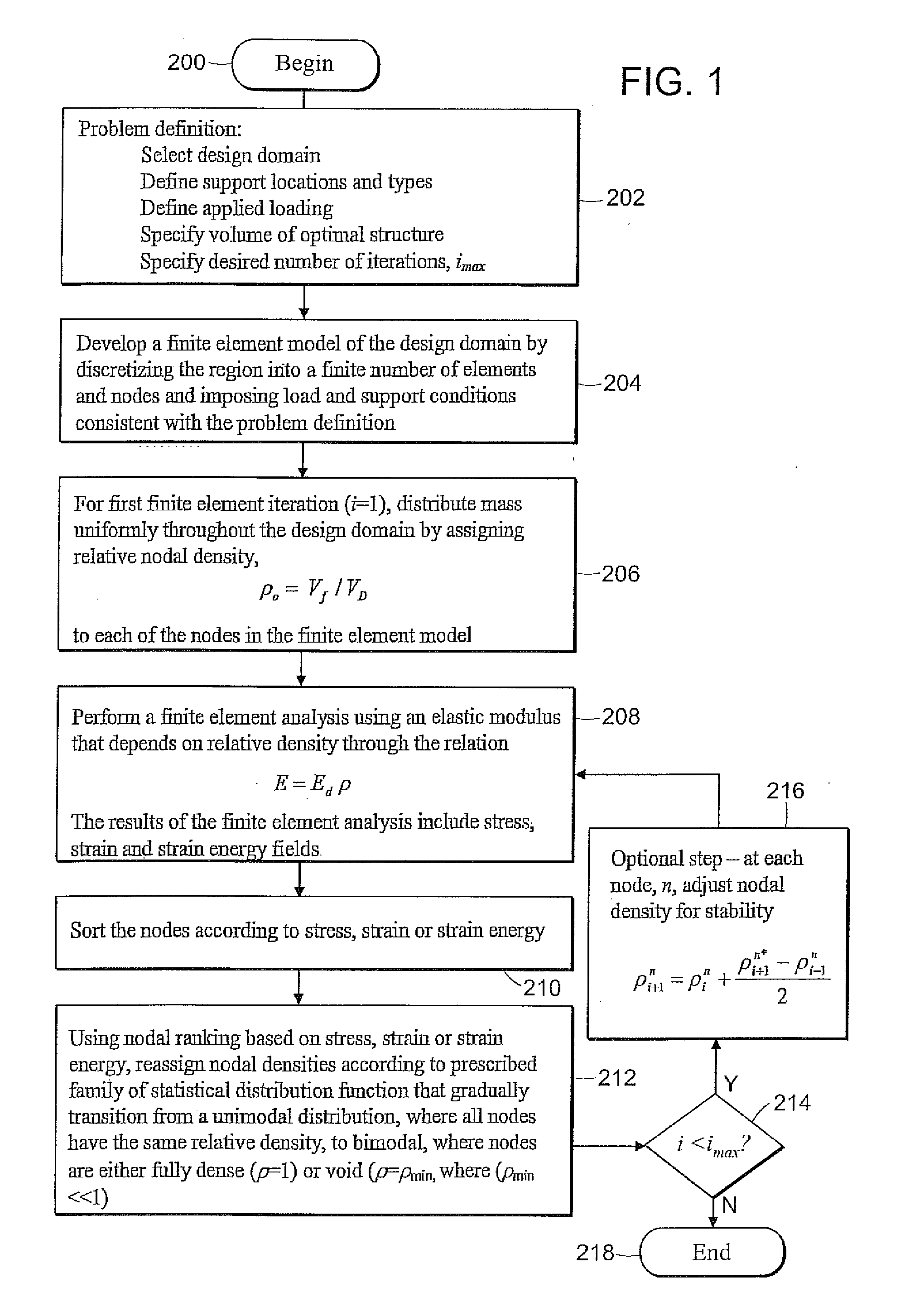
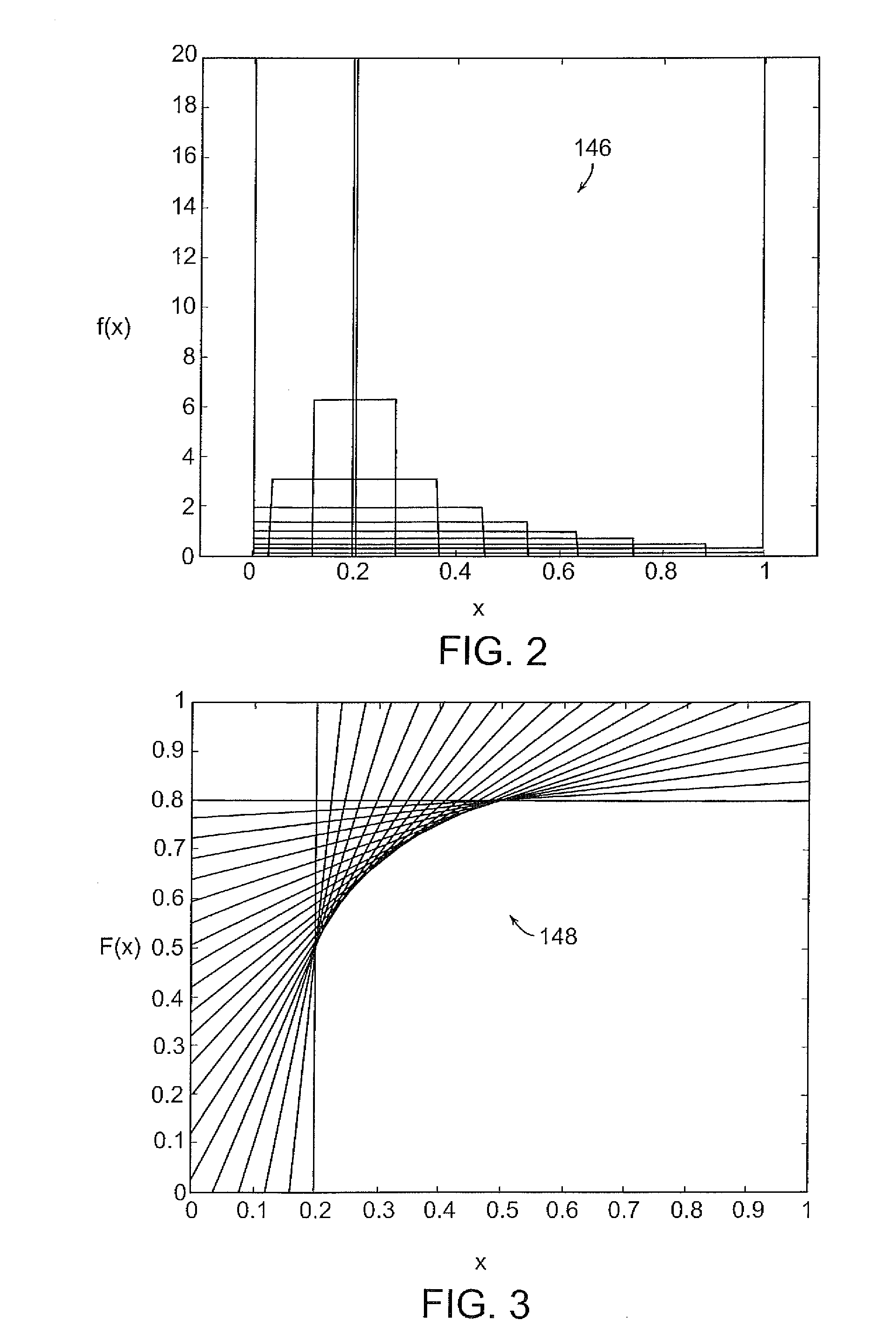
[0008]The invention provides a method for providing an optimal topology for a structure based on a set of design criteria including at least one support point and at least one force to be applied to the structure. The method includes the steps of identifying a plurality of nodes within a structure design domain, and assigning an initial density value to the plurality of nodes. The method also includes the steps of conducting a finite element analysis on the nodes, determining a stress intensity or strain energy value for each node, ranking the nodes by relative stress intensity or relative strain energy values, and adjusting the density value for each node. The method also includes the step of repeating the steps of conducting a finite element analysis on the nodes, determining the relative stress intensity or relative strain energy value for each node, ranking the nodes by relative stress intensity values, and adjusting the density value for each node through a predetermined number of steps to provide an optimal topology. This step process is carried out through a family of probability distribution functions which ensure a smooth transition from an initial uniform partial density state to a final bimodal state of voids and fully dense material regions. The use

Problems solved by technology

For more general loading configurations however, the optimal topology cannot be determined analytically and numerical procedures become necessary.
Studies have revealed however, that while the ESO method does provide reasonable results in some simple test cases, in more complicated problems it has been shown to fail to provide the optimal topology.
The homogenization method is more sophisticated than the ESO but, due to the use of a unique variational principal and the addition of specialized constraint equations, it is not amenible to being incorporated in standard finite element software.
The tedious computations involved in determination of effective Young's modulus and the need for customized finite element codes, pose significant limitations to homogenization methods.
Such methods, however, are also not immune to numerical instabilities and other limitations.

Method used


Image

  • Systems and methods for finite element based topology optimization
  • Systems and methods for finite element based topology optimization
  • Systems and methods for finite element based topology optimization

Examples


Embodiment Construction

iment of the invention;

[0018]FIG. 8 shows an illustrative diagrammatic view of the analytically optimal topology of the domain shown in FIG. 6 in accordance with an embodiment of the invention;

[0019]FIG. 9 shows an illustrative diagrammatic view of a minimum weight topology of a domain similar to that shown in FIG. 6 but for a dual strength material in accordance with an embodiment of the invention;

[0020]FIG. 10 shows an illustrative diagrammatic view of the analytically optimal topology of a domain similar to that shown in FIG. 6 but for a dual strength material in accordance with an embodiment of the invention;

[0021]FIG. 11 shows an illustrative diagrammatic view of a test case expected topology for a methodology of the invention for use on a three-dimensional structure;

[0022]FIG. 12 shows an illustrative diagrammatic view of a minimum weight topology of the test case shown in FIG. 11 in accordance with an embodiment of the invention.

[0023]The drawings are for illustrative purpose...


PUM


Abstract

A method is disclosed of providing an optimal minimum mass topology for a structure based on a set of design criteria including at least one support point and at least one force to be applied to the structure. The method includes the steps of: identifying a plurality of nodes within a structure design domain, and assigning an initial density value to said plurality of nodes; conducting a finite element analysis on the nodes; determining one of a stress intensity or strain energy values for each node; ranking the nodes by relative stress intensity or strain energy values; adjusting the density value for each node; and repeating the steps of conducting a finite element analysis on said nodes, wherein the step of adjusting each density value for each node is performed according to a family of statistical distribution functions that gradually transition to a bimodal distribution wherein nodes are either fully dense or effectively void thereby providing an optimal topology.

Description

PRIORITY INFORMATION[0001]This application is a continuation application of U.S. Ser. No. 12 / 137,160 filed Jun. 11, 2008, which is a continuation application of International Patent Application No. PCT / US2006 / 62302, filed on Dec. 19, 2006, which claims priority to U.S. Provisional Patent Application 60 / 751,500, filed on Dec. 19, 2005, all of which are incorporated herein by reference in their entirety.GOVERNMENT SPONSORSHIP[0002]This invention was sponsored by the National Science Foundation under Project Numbers R032532 and DMI0200058. The United States Government has certain rights to this invention.BACKGROUND[0003]The present invention relates generally to design optimization methodologies, and relates in particular to design methodologies for developing designs of structures to support a mass with a minimum amount of material.[0004]The design of minimal material (and therefore light-weight) structures is a subject of central importance in the development of a very wide range of ...

Claims


Application Information

Patent Timeline
IPC IPC(8): G06F17/50
CPCG06F2217/08G06F17/5018G06F2111/06G06F30/23G06F30/17
Inventor TAGGART, DAVID G.DEWHURST, PETERNAIR, ARUN U.
Owner BOARD OF GOVERNORS FOR HIGHER EDUCATION STATE OF RHODE ISLAND & PROVIDENCE PLANTATIONS
Learn More