
A deep space exploration aircraft power supply system

A technology for power supply systems and deep space exploration, applied in collectors, photovoltaic power generation, electric vehicles, etc., can solve the problem of reducing system current density, low effective power utilization of solar cell arrays, and inability to complete high-current charging tasks well, etc. problems, to achieve the effect of increasing specific power, simplifying system architecture, and improving power utilization

Active Publication Date: 2019-04-05
中电科蓝天科技股份有限公司
View PDF12 Cites 6 Cited by
  • Summary
  • Abstract
  • Description
  • Claims
  • Application Information

AI Technical Summary

Problems solved by technology

[0002] The power system of deep space exploration aircraft needs to be designed by integrating the characteristics of high-orbit (GEO) satellites and low-orbit (LEO) satellites. Usually, the power system topology (such as "three The traditional "three-domain" S3R system and the "two-domain" S4R system, etc.) cannot well meet the mission of deep space exploration aircraft. , while the "two-domain" S4R system has the problem of low effective power utilization of the solar cell array
[0003] The patent document with the patent number 2016107977030 discloses a high-power and high-efficiency satellite power supply system based on high-voltage and low-voltage double buses. The first solar battery array to the sixth solar battery array in this patent document supply power for 28V electrical loads and nickel-cadmium battery packs , the seventh solar battery array to the eighth solar battery array supply power for 42V electrical loads and lithium-ion battery packs, and the high and low voltage bus system is used to reduce the current density of the system, but the solar battery arrays and electrical loads are grouped in this application document The power supply is fixed and cannot automatically adjust the power supply relationship between the solar cell array and the electric load, so a power system topology needs to be redesigned

Method used


Image

  • A deep space exploration aircraft power supply system
  • A deep space exploration aircraft power supply system
  • A deep space exploration aircraft power supply system

Examples


Embodiment Construction

[0023] Embodiments of the present invention are further described below in conjunction with the accompanying drawings:

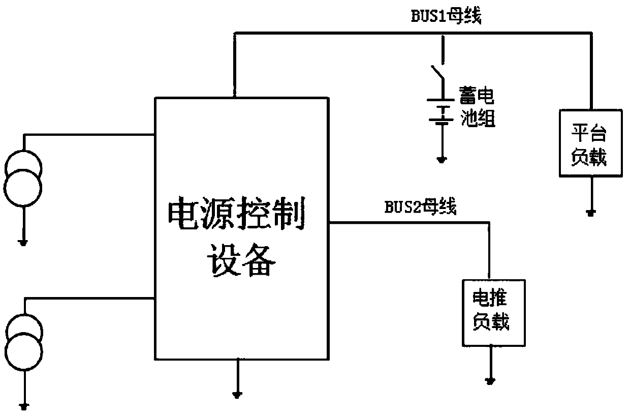
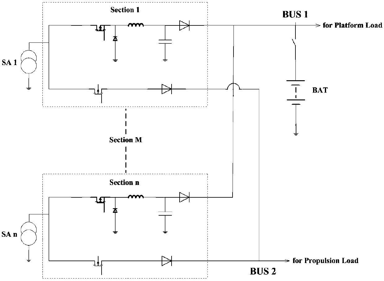
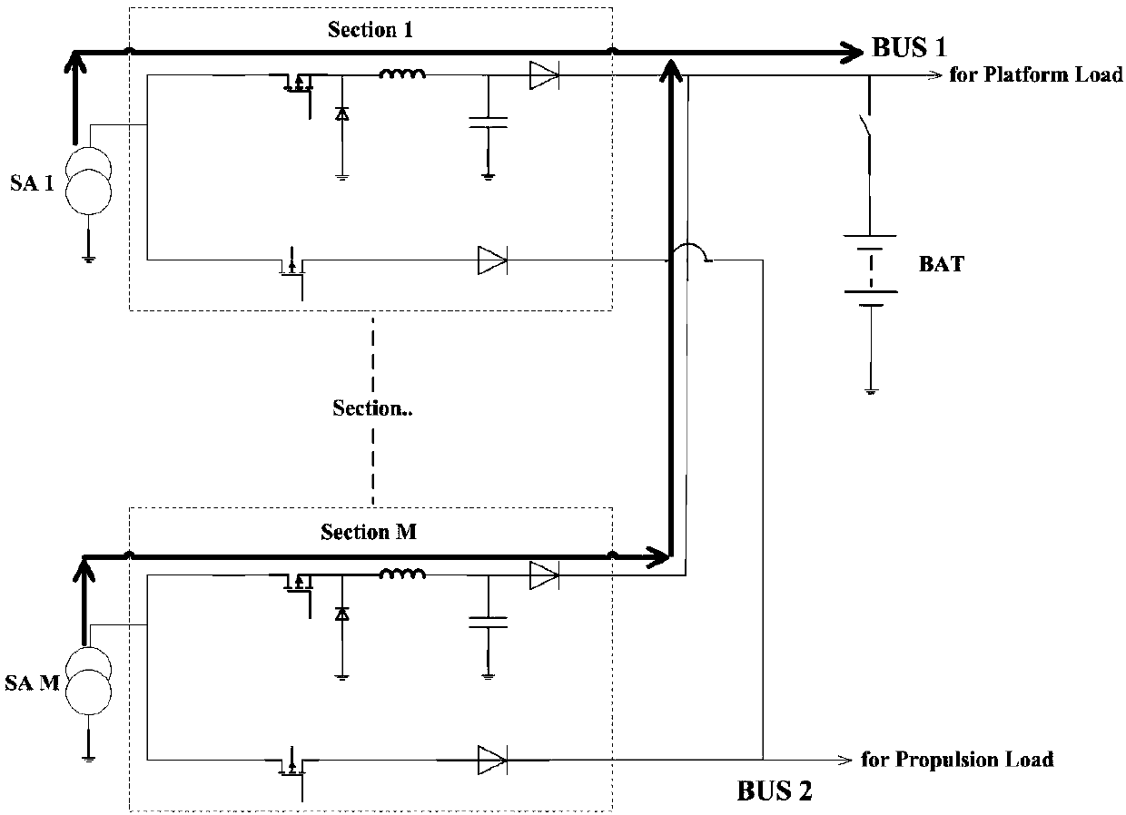
[0024] A power system for a deep space exploration aircraft, including a solar array, an energy storage battery pack, and power control equipment. The output power of the power system topology selects two independent buses: a semi-regulated BUS1 bus and an unregulated BUS2 bus. The BUS1 bus is mainly for the platform Load power supply, BUS2 bus is mainly for electric propulsion load power supply. The solar battery array supplies power to the BUS1 bus and BUS2 bus. The energy storage battery pack is connected to the BUS1 bus using a lithium-ion battery pack to meet the long-term load requirements of the platform load. The power control device is the core control unit of the power system and is responsible for regulating the solar battery. The array output power forms two power supply buses, and completes the charging and discharging management functions of th...


PUM


Abstract

A deep space exploration aircraft power supply system includes a solar battery array, an energy storage battery pack and a power supply control device. The output power of the power supply system topology selects from two independent buses: a semi-regulated BUS1 bus and a non-regulated BUS2 bus. The BUS1 bus mainly supplies a platform with electric power. The BUS2 bus mainly supplies an electric propulsion load with electric power. The solar battery array supplies the semi-regulated bus and the non-regulated bus with power sequentially. The system has high current charging capability. The double bus form optimizes the system topology. The power supply system design has high current charging capability. The power utilization of the solar array in the power supply system is raised.

Description

technical field [0001] The invention belongs to the technical field of space power supply control, in particular to a power supply system suitable for deep space exploration aircraft. Background technique [0002] The power system of deep space exploration aircraft needs to be designed by integrating the characteristics of high-orbit (GEO) satellites and low-orbit (LEO) satellites. Usually, the power system topology (such as "three Neither the "three-domain" S3R system nor the "two-domain" S4R system can well meet the mission of deep space exploration aircraft. The limitation of the traditional "three-domain" S3R system is that it cannot well complete the task of high-current charging in a short period of time. , while the "two-domain" S4R system has the problem of low effective power utilization of the solar array. [0003] The patent document with the patent number 2016107977030 discloses a high-power and high-efficiency satellite power supply system based on high-voltage...

Claims


Application Information

Patent Timeline
Patent Type & Authority Applications(China)
IPC IPC(8): H02J7/35
CPCH02J7/35Y02E10/56
Inventor 李建平张伟韩娜
Owner 中电科蓝天科技股份有限公司
Learn More