Stator for axial clearance type motor and axial clearance type motor

An axial gap and motor technology, applied in the field of electric motors, can solve the problems of increased cost, structural obstacles to the increase of maximum power, and inability to effectively improve the specific power of axial gap motors, so as to achieve the improvement of specific power and maximum power. Effect

Active Publication Date: 2012-08-01
HAIMA AUTOMOBILE CO LTD +2
View PDF7 Cites 16 Cited by
  • Summary
  • Abstract
  • Description
  • Claims
  • Application Information

AI Technical Summary

Problems solved by technology

[0003] However, the existing technology often pays more attention to how to improve various factors that directly affect the maximum power, such as heat dissipation effect, magnetic gathering performance, and maximum torque, so as to increase the maximum power of the axial gap motor, but at the same time, it is It is difficult to prevent the structure of the axial gap type motor from being complicated, and thus resulting in an increase in the mass of the axial gap motor
[0004] Therefore, the existing technology cannot really effectively improve the specific power of the axial gap motor, and it may further hinder the improvement of the maximum power due to the complexity of the structure, and lead to an increase in cost

Method used


Image

  • Stator for axial clearance type motor and axial clearance type motor
  • Stator for axial clearance type motor and axial clearance type motor
  • Stator for axial clearance type motor and axial clearance type motor

Examples


Embodiment Construction

[0035] In order to make the object, technical solution and advantages of the present invention clearer, the present invention will be further described in detail below with reference to the accompanying drawings and examples.

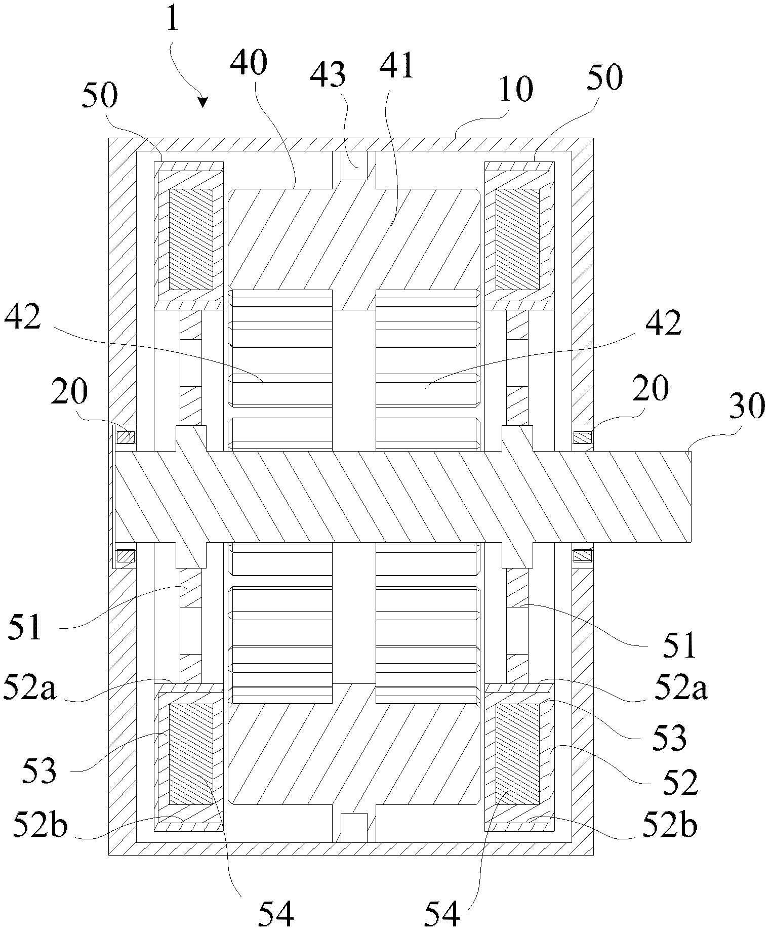
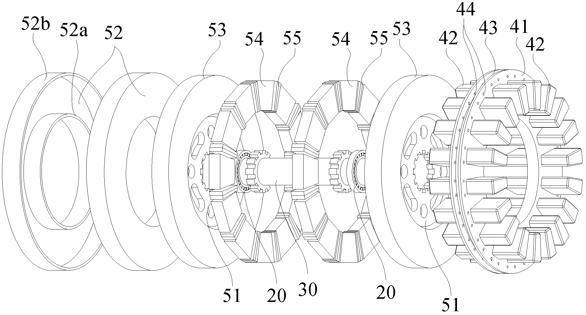
[0036] figure 1 It is an assembly sectional view of the axial gap motor in the specific embodiment of the present invention. figure 2 It is an exploded schematic diagram of an axial gap motor in a specific embodiment of the present invention.

[0037] See figure 1 and figure 2 , the axial gap motor 1 in the specific embodiment of the present invention includes: a housing 10 (not in figure 2 Shown in), two bearings 20, a rotating shaft 30, a stator 40, two rotors 50. in:

[0038] The shell 10 has two opposite end faces and a closed surrounding peripheral face;

[0039] The two bearings 20 are respectively arranged on the two end surfaces of the housing 10;

[0040] The rotating shaft 30 is carried by two bearings 20;

[0041] The stator 40 is ...


PUM


Abstract

The invention provides a stator for an axial clearance type motor and the axial clearance type motor. Stator teeth stator windings are symmetrically arranged on the two end faces of the stator to support the axial clearance type motor to adopt a dual-rotor mode which can make the stress of a rotating shaft balanced, so that improvement in the bearable maximum torque and rotating speed of the axial clearance type motor is facilitated. In addition, a stator slot formed on the stator replaces a collector ring and a cooling shell, so that the structure of the axial clearance type motor can be simplified. Moreover, clearance slots of the stator are equal in width along a radial direction, so that the utilization of air clearances is improved; and chambers are formed at the end part edges of the stator teeth of the stator, so that the dispersion of lines of magnetic force can be suppressed. Therefore, the specific power of the axial clearance type motor can be improved.

Description

technical field [0001] The invention relates to motor technology, in particular to a rotor of an axial gap motor and an axial gap motor using the stator. Background technique [0002] Axial gap motor is the core power component of electric vehicles, and its power performance plays a vital role in electric vehicles. Among them, the specific power is an index used to measure the dynamic performance of the axial gap motor, and the specific power is equal to the ratio of the maximum power to the mass of the axial gap motor. [0003] However, the existing technology often pays more attention to how to improve various factors that directly affect the maximum power, such as heat dissipation effect, magnetic gathering performance, and maximum torque, so as to increase the maximum power of the axial gap motor, but at the same time, it is It is difficult to prevent the structure of the axial gap motor from being complicated, and thus resulting in an increase in the mass of the axial ...

Claims


Application Information

Patent Timeline
Patent Type & Authority Applications(China)
IPC IPC(8): H02K1/14H02K16/02H02K1/27
Inventor 景柱韩旭林斯瑜付鑫崔相雨周道辉
Owner HAIMA AUTOMOBILE CO LTD
Why Eureka
Try Eureka