Stepping motor control-based high-power electronic switch

A technology of stepping motors and electronic switches, applied to electric switches, power devices inside switches, circuits, etc., can solve problems such as high requirements for protection boxes, disconnected circuits, and small driving force, so as to improve electrical conductivity and prolong service life The effect of life and power improvement

Pending Publication Date: 2020-01-10
NINGBO HAIBEI ELECTRICAL APPLIANCE
View PDF0 Cites 1 Cited by
  • Summary
  • Abstract
  • Description
  • Claims
  • Application Information

AI Technical Summary

Problems solved by technology

[0003] In view of this, in order to solve the problem that the driving force of the traditional electronic switch is relatively small and the protection box of the traditional electronic switch is relatively high, the present invention proposes a high-power electronic switch based on stepping motor control, which does not use the traditional The relay control structure uses Hall elements to control the forward and reverse rotation of the motor shaft of the stepping motor, thereby driving the swing arm on the motor shaft of the stepping motor to rotate forward and reverse, and the swing arm can drive the flow of heavy loads The contact shrapnel moves, so as to realize contact and separation with the extra-thick current-carrying static contact shrapnel. When the extra-thick current-carrying contact shrapnel contacts with the extra-thick current-carrying static contact shrapnel, the entire circuit Conduction, when the extra-thick current-carrying contact conductive shrapnel separates from the extra-thick current-carrying static contact shrapnel, the entire circuit is disconnected

Method used


Image

  • Stepping motor control-based high-power electronic switch
  • Stepping motor control-based high-power electronic switch
  • Stepping motor control-based high-power electronic switch

Examples


specific Embodiment example 1

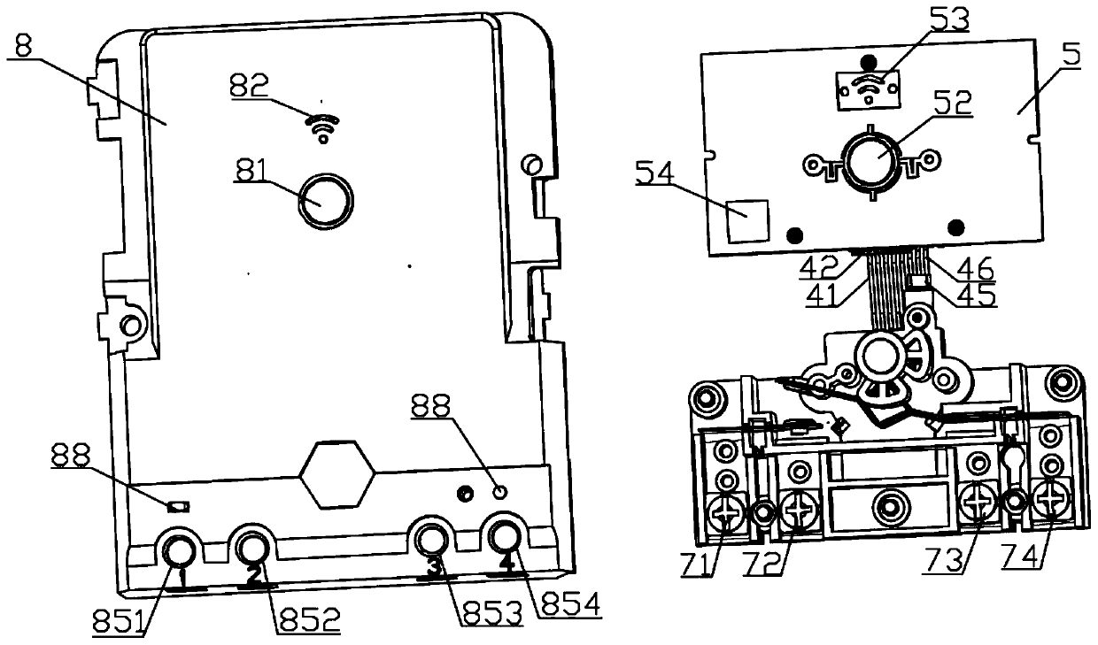
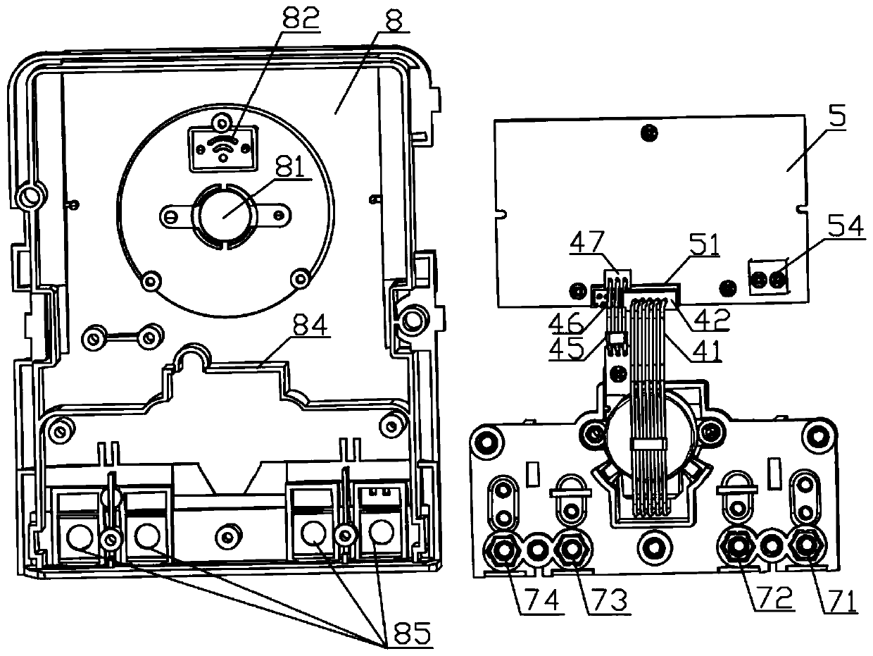
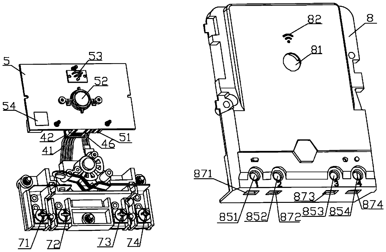
[0039] Such as Figure 1~4 As shown, it is an explosion diagram of a high-power electronic switch based on stepping motor control, such as Figure 6-11 Shown is the structural schematic diagram of the main body of the electronic switch. A high-power electronic switch based on stepping motor control, which includes: an electronic switch main body and a fixed box 8, the electronic switch main body includes an extra-thick current-carrying static contact conductive shrapnel 1, an extra-thick current-carrying static contact conductive shrapnel 2, L Shaped conductive shrapnel fixed plate 3, PCB board 5, plastic base 6, are characterized in that: also include stepper motor 4 and Hall element 45, stepper motor 4 is electrically connected with PCB board 5, stepper motor 4 and Hall element The Hall element 45 is electrically connected, the Hall element 45 is electrically connected to the PCB board 5, the power line of the PCB board 5 can be electrically connected to the load, and the n...

specific Embodiment example 2

[0047] Such as Figure 5 Shown is an exploded view of a high-power electronic switch based on stepper motor control. The difference with the specific implementation case 1 is that the high-power electronic switch based on stepping motor control also includes a protective case 9, and the protective case 9 includes an upper cover 91 and a lower cover 92, and the side of the upper cover 91 is provided with a first fixed shaft 911 and the second fixed shaft 912, the side of the lower cover 92 is provided with a first shaft sleeve 921 and a second shaft sleeve 922, the first fixed shaft 911 passes through the first shaft sleeve 921, and the second fixed shaft 912 passes through the second shaft sleeve 922, and the first fixed shaft 911 and the second fixed shaft 912 rotate synchronously in the first shaft sleeve 921 and the second shaft sleeve 922, so that the upper cover 91 and the lower cover 92 can be opened and closed, and the other one of the upper cover 91 A buckle frame 913...


PUM


Abstract

The provides a stepping motor control-based high-power electronic switch and aims to solve the problems of small driving force and high requirements for a protection box of a traditional electronic switch. The stepping motor control-based high-power electronic switch comprises an electronic switch main body and a fixed box 8; the electronic switch body comprises an extra-thick current-carrying static contact conductive elastic sheet 1, an extra-thick current-carrying moving contact conductive elastic sheet 2, L-shaped conductive elastic sheet fixing plates 3, a PCB 5 and a plastic base 6. Thehigh-power electronic switch is characterized in that the high-power electronic switch comprises a stepping motor 4 and a Hall element 45; the stepping motor 4 is electrically connected with the PCB 5; the stepping motor 4 is electrically connected with the Hall element 45; the Hall element 45 is electrically connected with the PCB 5; the power source line of the PCB 5 can be electrically connected with a load; the number of the L-shaped conductive elastic sheet fixing plates 3 is at least two; and the two L-shaped conductive elastic sheet fixing plates 3 are fixed on the first surface of theplastic base 6.

Description

[0001] The invention belongs to the technical field of timers, and more specifically relates to a high-power electronic switch based on stepping motor control. Background technique [0002] Most of the traditional electronic switches are mainly controlled by relays. The volume of the relay is relatively small, so the power is relatively small. Usually, the maximum power of the traditional electronic switch is 2HP (HP is the abbreviation of horsepower, Chinese horsepower). Traditional electronic switches are mainly used to drive loads such as motors. As the load increases, the power requirements for electronic switches are also increasing. When the load increases to a certain extent, traditional electronic switches cannot be driven. Therefore, the load that can be driven by electronic switches is relatively limited. Furthermore, traditional electronic switches are placed directly in the protective box, so the requirements for the protective box are relatively high. Contents o...

Claims


Application Information

Patent Timeline
Patent Type & Authority Applications(China)
IPC IPC(8): H01H1/02H01H3/26
CPCH01H1/02H01H3/26H01H2003/266
Inventor 文毅
Owner NINGBO HAIBEI ELECTRICAL APPLIANCE
Why Eureka
Try Eureka