Excavator control system with oil hybrid power

An oil-liquid mixing and control system technology, applied in the direction of earth mover/shovel, construction, etc., can solve the problems of energy waste, large size of system components, high price, reduce heat generation, simplify system design, and improve recovery efficiency Effect

Active Publication Date: 2015-01-28
XCMG EXCAVATOR MACHINERY
View PDF4 Cites 17 Cited by
  • Summary
  • Abstract
  • Description
  • Claims
  • Application Information

AI Technical Summary

Problems solved by technology

[0004] Whether it is to recover the rotary overflow energy or the potential energy of the boom separately, a part of the energy will be wasted; when the boom is lowered, the output power density of the oil cylinder is high, so the power density of the hybrid power system is also high, which will cause system failure. The component size is too large and the price is high, so it is not suitable to recover the potential energy of the boom in the existing hybrid electric excavator system

Method used


Image

  • Excavator control system with oil hybrid power
  • Excavator control system with oil hybrid power
  • Excavator control system with oil hybrid power

Examples


Embodiment Construction

[0024] The present invention will be further described below in conjunction with accompanying drawing.

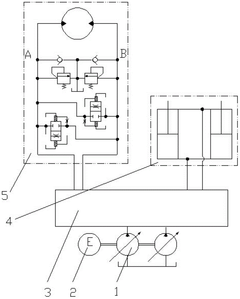
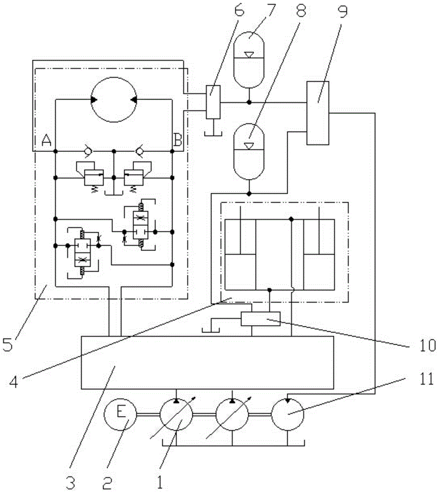
[0025] Such as figure 2 As shown, an oil-hydraulic hybrid excavator control system includes a hydraulic pump 1, an engine 2, a main control valve 3, a boom cylinder 4, a swing motor 5, a swing energy recovery valve 6 and a boom potential energy recovery valve 10, The two oil inlets of the rotary energy recovery valve 6 are respectively connected to the A port and the B port of the rotary motor 5, and the oil outlet of the rotary energy recovery valve 6 is connected to the rotary accumulator 7;

[0026] The oil inlet of the boom potential energy recovery valve 10 is connected with the rodless cavity of the boom cylinder 4, and the oil outlet of the boom potential energy recovery valve 10 is connected with the boom accumulator 8;

[0027] The oil outlets of the slewing accumulator 7 and the boom accumulator 8 are connected with the oil inlet of the energy release control va...


PUM


Abstract

The invention relates to a hydraulic excavator control system, particularly to an excavator control system with oil hybrid power, and belongs to the technical field of engineering machinery. The system comprises hydraulic pumps (1), an engine (2), a main control valve (3), a boom cylinder (4), a rotary motor (5), a rotary energy recovery valve (6) and a movable arm potential energy recovery valve (10), wherein the rotary energy recovery valve recovers the overflowing energy of the rotary motor into a rotary energy accumulator (7); the movable arm potential energy recovery valve recovers the potential energy of the boom cylinder into a movable arm energy accumulator; oil outlets of the rotary energy accumulator and the movable arm energy accumulator are both connected with an energy release control valve, recovered energy is controlled to be transported to an auxiliary motor (11), and the auxiliary motor and the engine jointly provide power for the hydraulic pumps. Through the adoption of the system disclosed by the invention, the movable arm potential energy and the rotary overflowing energy can both be recovered into the energy accumulators and can provide auxiliary power for the system when required, and the lost energy of the excavator system can be furthest recovered.

Description

technical field [0001] The invention relates to a hydraulic excavator control system, in particular to an oil-liquid hybrid power excavator control system, which belongs to the technical field of engineering machinery. Background technique [0002] Due to its large consumption, high fuel consumption and poor emission, hydraulic excavators have gradually become the object of general attention in the field of energy conservation and environmental protection. The control system of the existing hydraulic excavator such as figure 1 As shown, the engine 2 drives the hydraulic pump 1 to extract the hydraulic oil in the oil tank and sends it to the hydraulic swing motor 5 and the boom cylinder 4 through the main control valve 3 . Due to the large mass of the turntable, boom, stick and bucket of the hydraulic excavator, a large amount of inertial energy will be released when decelerating or braking. An effective way to solve this problem is to perform energy recovery. Generally, th...

Claims


Application Information

Patent Timeline
Patent Type & Authority Applications(China)
IPC IPC(8): E02F9/20E02F9/22
Inventor 秦家升王振兴费树辉史继江孙本强刘实现尹超董玉忠夏炎牛东东王绪通孙忠永郑华
Owner XCMG EXCAVATOR MACHINERY
Why Eureka
Try Eureka