Combustor assembly for a turbine engine that mixes combustion products with purge air

a turbine engine and combustion product technology, applied in the direction of machines/engines, mechanical equipment, lighting and heating apparatus, etc., can solve the problem that the pilot flame is known to be a significant contributor to undesirable effects

Inactive Publication Date: 2011-07-14
GENERAL ELECTRIC CO
View PDF4 Cites 16 Cited by
  • Summary
  • Abstract
  • Description
  • Claims
  • Application Information

AI Technical Summary

Problems solved by technology

However, the pilot flame is known to be a significant contributor...

Method used


Image

  • Combustor assembly for a turbine engine that mixes combustion products with purge air
  • Combustor assembly for a turbine engine that mixes combustion products with purge air
  • Combustor assembly for a turbine engine that mixes combustion products with purge air

Examples


Embodiment Construction

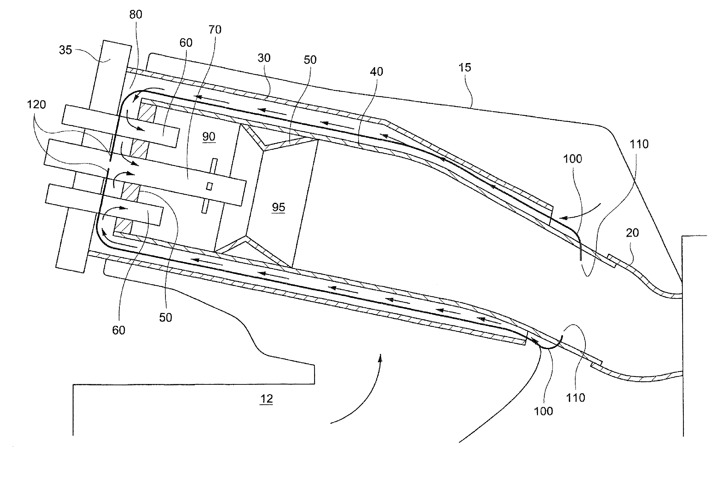
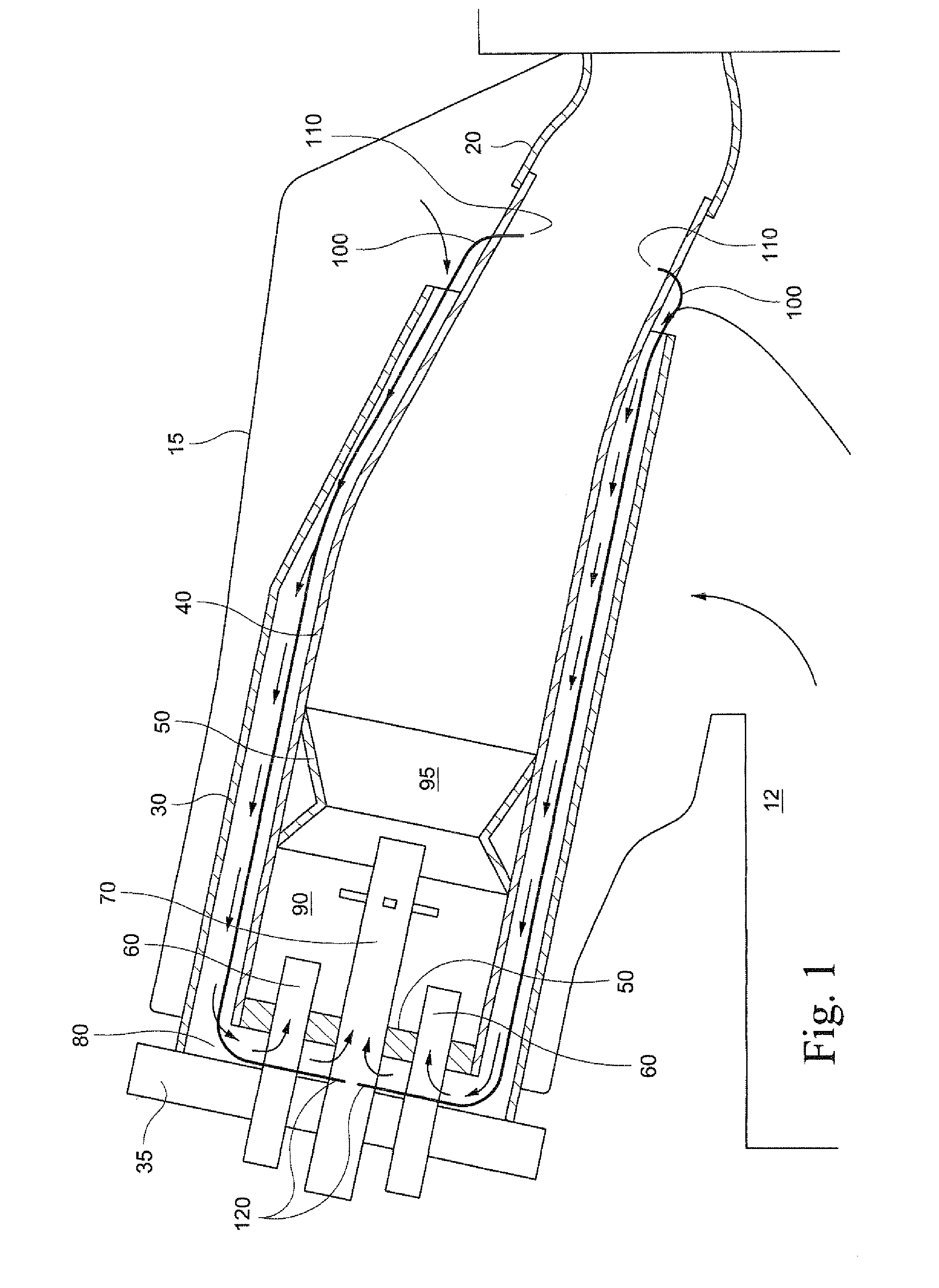
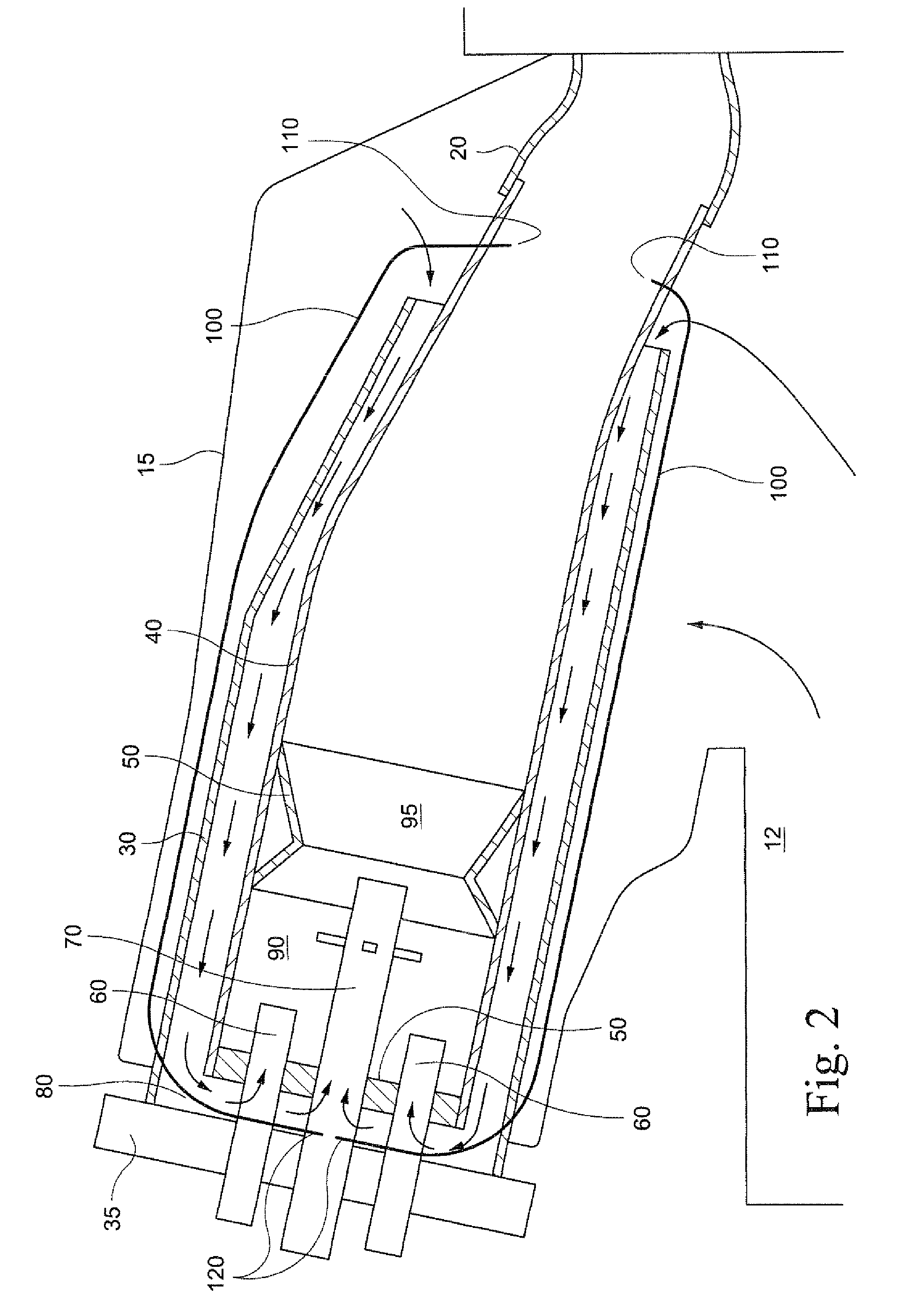
[0014]A typical combustor assembly for a turbine engine is illustrated in FIG. 1. As shown therein, the combustor includes a transition duct 20 which routes combustion gases into the turbine section of the turbine engine. The transition duct 20 is attached to a downstream end of a combustor liner 40. A flow sleeve 30 surrounds the exterior of the combustor liner 40.

[0015]Compressed air from the compressor section 12 of the turbine is routed into the annular space between the combustor liner 40 and the flow sleeve 30. The arrows in FIG. 1 illustrate the direction of movement of the compressed air. As shown in FIG. 1, the compressed air moves along the annular space between the combustor liner 40 and the flow sleeve 30 to the upstream end of the combustor. The compressed air then turns and enters the space inside the combustor liner 40.

[0016]A plurality of fuel nozzles 60, 70 are located at the upstream end of the combustor. Multiple primary fuel nozzles 60 are mounted in an annular r...


PUM


Abstract

A combustor assembly for a turbine engine includes a fuel nozzle located at an upstream end of the combustor assembly. The fuel nozzle includes both a fuel delivery passageway and a purge air passageway. The purge air passageway conveys a flow of purge air to cool the fuel nozzle. The combustor assembly also includes a combustion product return line that conveys a flow of combustion products from a position downstream of a combustion zone of the combustor back to the fuel nozzle. The combustion products are mixed with purge air, and the mixture is delivered into a combustion zone located just downstream of the fuel nozzle. The addition of the combustion products into the purge air reduces the amount of oxygen in mixed flow, which helps to reduce the generation of undesirable nitrogen oxide combustion byproducts. Also, the greater heat of the combustion products helps to increase the temperature of the mixture, which helps to maintain the stability of a pilot flame fed by the mixture.

Description

BACKGROUND OF THE INVENTION[0001]Turbine engines used in the electrical power generation industry typically include a compressor section which is surrounded by a plurality of combustors. In each combustor, compressed air from the compressor section of the turbine is introduced into an interior of a combustor liner. The compressed air is mixed with fuel, and the air-fuel mixture is then ignited. The combustion gases then pass out of the combustor and into the turbine section of the engine.[0002]Fuel nozzles are mounted at the upstream end of the combustor liner, and the fuel nozzles deliver fuel into the flow of compressed air to create the air-fuel mixture that is burned. The fuel nozzles can include primary fuel nozzles that are arranged in an annular ring around the combustor, and a secondary fuel nozzle that is located in the center of the combustor. Typically, the primary fuel nozzles will deliver an air-fuel mixture into a primary combustion zone. The secondary fuel nozzle, whi...

Claims


Application Information

Patent Timeline
IPC IPC(8): F02C7/22F02C7/00
CPCF23C9/00F23R3/343F23L7/00F23K2301/203F23K2300/203
Inventor SINGH, ARJUNKRAEMER, GILBERT OTTO
Owner GENERAL ELECTRIC CO
Why Eureka
Try Eureka