

M240 rifle with select fire mechanism for selective fully-automatic and semi-automatic operation
a fully automatic and semi-automatic technology, applied in the field of m240 machine guns, can solve the problems that the m240, once converted to semi-automatic fire, is not readily converted back to fully automatic fir
- Summary
- Abstract
- Description
- Claims
- Application Information
AI Technical Summary
Benefits of technology
Problems solved by technology
Method used
Image

Examples
Embodiment Construction
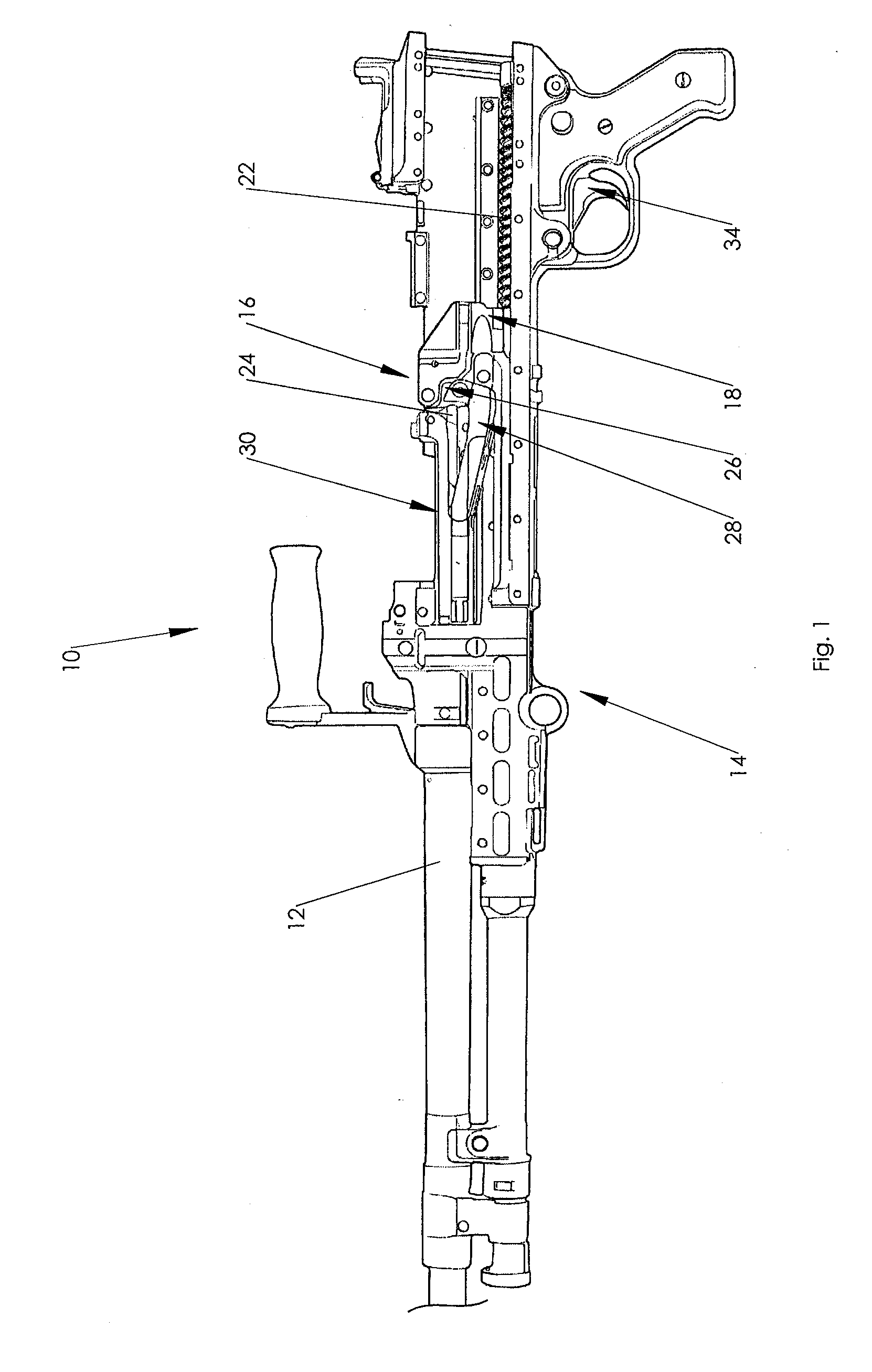
[0016]This invention relates to the M240 Automatic Rifle, Caliber 7.62×51 mm, including the known model variations. A portion of such a rifle is depicted in FIG. 1 and is indicated generally by the numeral 10. The rifle 10 includes a barrel 12, threadably carried by a receiver 14. The receiver houses a striking mechanism 16. The striking mechanism 16 includes a gas operated op rod assembly, indicated generally by the numeral 18, which reciprocates in a gas cylinder beneath the barrel 12. The gas cylinder receives some of the expanding gases resulting from the firing of a cartridge, and these expanding gases impinge upon a piston portion of the op rod assembly 18. Thus, the op rod assembly 18 is driven rearward (to the right in FIG. 1), away from the muzzle of the barrel by gases formed when a cartridge is fired, and is then driven forward (to the left in FIG. 1) by a return spring 22.
[0017]The forward and backward movement of the op rod assembly 18 cycles internal components, common...
PUM
 Abstract
Description
Claims
Application Information