Mask frame assembly for thin film deposition

Active Publication Date: 2011-07-14
SAMSUNG DISPLAY CO LTD
View PDF27 Cites 41 Cited by
  • Summary
  • Abstract
  • Description
  • Claims
  • Application Information

AI Technical Summary

Benefits of technology

[0033]In the mask frame assembly for thin film deposition according to embodiments of the present invention, a plurality of unit masks

Problems solved by technology

However, it is difficult to achieve high light-emission efficiency with such a structure, and thus, intermediate layers, including an electron injection layer, an electron transport layer, a hole transport layer, a hole injection lay

Method used


Image

  • Mask frame assembly for thin film deposition
  • Mask frame assembly for thin film deposition
  • Mask frame assembly for thin film deposition

Examples


Embodiment Construction

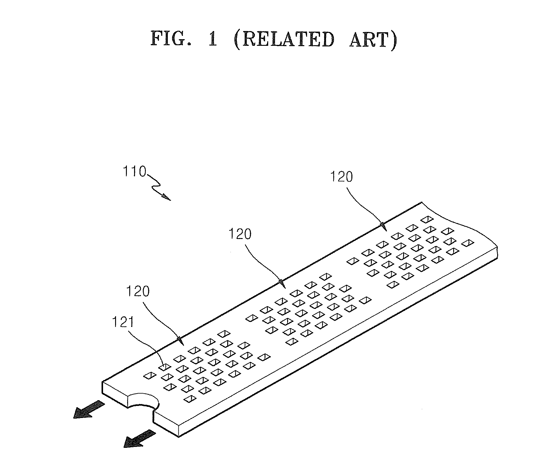
[0045]FIG. 1 is a perspective view partially illustrating a unit mask 110 of a conventional mask frame assembly.

[0046]Referring to FIG. 1, the unit mask 110 is formed of a strip-form thin film and includes a plurality of unit masking patterns 120 formed on the thin film along a longitudinal direction thereof.

[0047]The plurality of unit masking patterns 120 each includes a plurality of openings 121 for deposition. The openings 121 may have dot patterns, each of which is discontinuously formed, or stripe patterns that are continuously formed.

[0048]Here, while manufacturing the mask frame assembly, wrinkles may be generated in the unit mask 110 due to a tensile force exerted on the unit mask 110 in a direction shown by arrows. When the tensile force of the unit mask 110 is reduced, wrinkles might not be generated. For example, the unit mask 110 may be extended to a point just before the onset of wrinkling. However, when the tensile force of the unit mask 110 is significantly reduced, a...


PUM

PropertyMeasurementUnit
Thicknessaaaaaaaaaa
Widthaaaaaaaaaa

Abstract

A mask frame assembly for thin film deposition includes a frame having an opening and at least two unit masks having end parts in a longitudinal direction fixed to the frame, each of the unit masks comprising first regions and second regions, the first regions having unit masking patterns, each of the unit masking patterns having a plurality of openings for thin film deposition, the unit masking pattern being spaced apart from each other, each of the second regions being interposed between a pair of adjacent ones of the first regions, the first regions having a first thickness from a first surface of the unit masks, and at least a portion of the second regions having a second thickness from a second surface of the unit masks opposite to the first surface of the unit masks, such that the first regions and the at least the portion of the second regions are offset from each other in a direction normal to the first and second surfaces. A plurality of unit masks are each half etched from different surfaces and thus a height of wrinkles generated in the mask of the mask frame assembly may be reduced.

Description

CROSS-REFERENCE TO RELATED APPLICATION[0001]This application claims priority to and the benefit of Korean Patent Application No. 10-2010-0002379, filed on Jan. 11, 2010, in the Korean Intellectual Property Office, the disclosure of which is incorporated herein in its entirety by reference.BACKGROUND[0002]1. Field[0003]The present invention relates to a mask frame assembly for thin film deposition.[0004]2. Description of Related Art[0005]In general, organic light-emitting display devices have a larger viewing angle, better contrast characteristics, and a faster response speed than other display devices.[0006]Organic light-emitting display devices generally have a stacked structure including an anode, a cathode, and an emission layer interposed between the anode and the cathode, and display images in color when holes and electrons, injected respectively from the anode and the cathode, recombine in the emission layer, thereby emitting light. However, it is difficult to achieve high lig...

Claims


Application Information

Patent Timeline
IPC IPC(8): C25D1/10B05C11/00
CPCC23C14/042C23C14/12G03F1/10H01L51/0011C25D1/10C23F1/02H10K71/166G03F1/68
Inventor LEE, CHOONG-HOLEEOH, YOON-CHAN
Owner SAMSUNG DISPLAY CO LTD
Why Eureka
Try Eureka