Heat exchanger

Inactive Publication Date: 2011-07-14
ASIA VITAL COMPONENTS SHENZHEN CO LTD
View PDF8 Cites 8 Cited by
  • Summary
  • Abstract
  • Description
  • Claims
  • Application Information

AI Technical Summary

Benefits of technology

[0016]In order to solve the above problems, an objective of the present invention is to provide a heat exchanger having a spiral guiding trough, whereby the thermal-conducting capacity and the coefficient of thermal performance can be increased.
[0017]In order to achieve the above objective, the present invention is to provide a heat exchanger, which includes: a body having a center and a spiral guiding trough extending spirally and outwardly from the center to an outside of the center, a radius of the spiral guiding trough increasing gradually from the center to the outside of the center; and a first port and a second port in communication with the spiral guiding trough respectively. With the spiral guiding trough, a fluid can be mixed sufficiently in the spiral guiding trough, thereby achieving an excellent thermal-conducting effect.

Problems solved by technology

However, since electronic elements in the electronic apparatuses generate waste heat during their operation at high speed, the waste heat ma be accumulated in the electronic apparatuses if the waste heat cannot be dissipated to the outside of the electronic apparatuses.
As a result, the temperature of the electronic elements inside the electronic apparatus increases continuously, which causes the electronic elements to suffer damage or deteriorate the efficiency in operation due to its high temperature.
However, the amount of airflow generated by the heat-dissipating fan is so limited that the heat-dissipating effect and the degree of lowering the temperature are restricted.
Although the aforesaid water-cooling heat-dissipating device can generate a better heat-dissipating effect than that of air cooling, another problem is generated.
Further, the cooling liquid stayed in the water-cooling heat-dissipating device is so short that the cooling liquid is rapidly exhausted from the outlet port even not absorbing enough heat.
As a result, the water-cooling effect is insufficient, which also affects the thermal-conducting effect and the heat-dissipating effect.
Therefore, the whole heat-exchanging efficiency, the thermal-conducting effect and in turn the heat-dissipating effect of the whole structure are insufficient.
(1) the amount of the cooling liquid in the base is so small that the thermal-conducting effect is poor;
(2) only a lower layer of the cooling liquid is brought into thermal contact with a heat source, so that the thermal-conducting effect is poor;
(3) poor heat-exchanging efficiency; and
(4) poor heat-dissipating effect.

Method used


Image

  • Heat exchanger
  • Heat exchanger
  • Heat exchanger

Examples


first embodiment

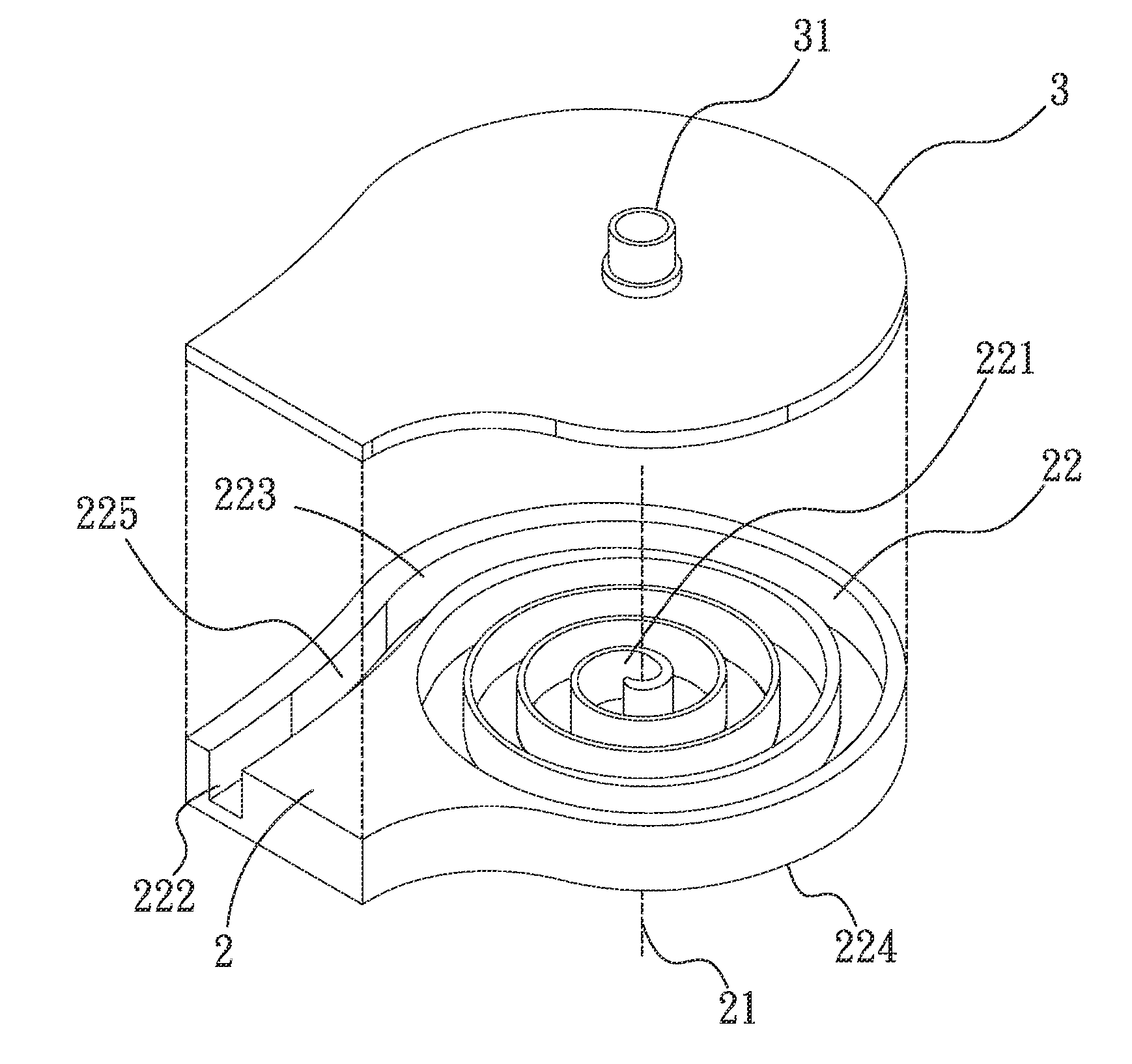
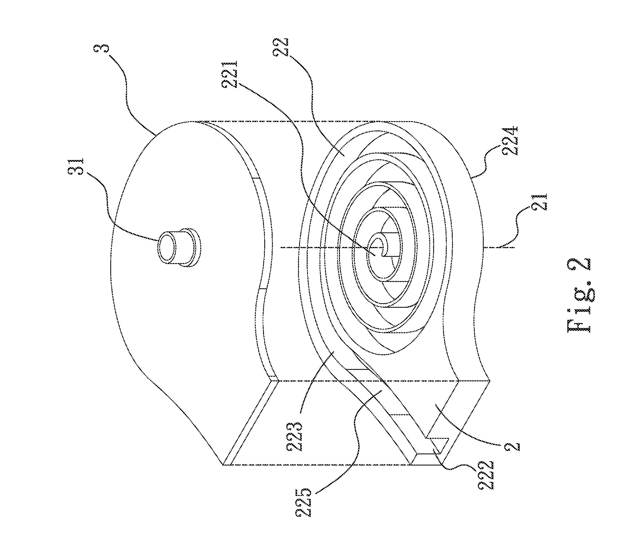
[0037]The present invention is directed to a heat exchanger. The drawings show several preferred embodiments of the present invention. Please refer to FIGS. 2 to 5. The heat exchanger of the present invention includes a body 2 having a center 21 as shown by a dotted axis. A spiral guiding trough 22 extends spirally and outwardly from the center 21 to the outside of the center 21. The radius of the spiral guiding trough 22 increases gradually from the center 21 to the outside of the center 21. In other words, the spiral guiding trough 22 extends spirally toward the inner wall of the body 2, thereby forming a spiral channel (i.e. the spiral guiding trough 22). FIG. 2 shows the spiral guiding trough 22.

[0038]The body 2 further has a first port 221 and a second port 222. The first port 221 is provided in the center 21, and the second port 222 is provided at the outside of the center 21. The first port 221 and the second port 222 are in communication with the spiral guiding trough 22.

[00...

third embodiment

[0047]Please refer to FIGS. 7 to 9, which show the present invention. The third embodiment is substantially the same as the first embodiment, and thus the redundant description is omitted thereto. The only difference between the third embodiment and the first embodiment lies in that the heat exchanger further includes at least one first turbulent unit 4 provided on a wall surface 226 of the spiral guiding trough 22. In the present embodiment, the first turbulent unit 4 is provided on the closed side 224 of the spiral guiding trough 22. The first cover 3 has at least one second turbulent unit 5 facing the open side 223 of the spiral guiding trough 22. Thus, in the present embodiment, the first turbulent unit 4 and the second turbulent unit 5 are provided on the closed side 224 and the open side 223 of the spiral guiding trough 22 respectively. The first turbulent unit 4 and the second turbulent unit 5 are protrusions provided on the closed side 224 and the open side 223 of the spiral...


PUM


Abstract

A heat exchanger includes a body having a center and a spiral guiding trough extending spirally and outwardly from the center toward an outside of the center. The radius of the spiral guiding trough increases gradually from the center toward the outside of the center. A first port and a second port are in communication with the spiral guiding trough respectively. With the combination of the spiral guiding trough and the body, the fluid can be sufficiently mixed in the spiral guiding trough, thereby achieving an excellent thermal-conducting effect.

Description

[0001]This application claims the priority benefit of Taiwan patent application number 099100907 filed on Jan. 14, 2010.BACKGROUND OF THE INVENTION[0002]1. Field of the Invention[0003]The present invention relates to a heat exchanger, and in particular to a heat exchanger with an increased thermal-conducting efficiency.[0004]2. Description of Prior Art[0005]With the continuous advancement of electronic information technology, electronic apparatuses (such as computers, notebook computer, communication housings, or the like) are getting more popular and widely used in our daily life. However, since electronic elements in the electronic apparatuses generate waste heat during their operation at high speed, the waste heat ma be accumulated in the electronic apparatuses if the waste heat cannot be dissipated to the outside of the electronic apparatuses. As a result, the temperature of the electronic elements inside the electronic apparatus increases continuously, which causes the electron...

Claims


Application Information

Patent Timeline
IPC IPC(8): F28D15/00F28F3/02F28F7/00
CPCF28F3/048F28F3/12F28F13/12H01L23/473H01L2924/0002H01L2924/00F28D9/04
Inventor CHANG, SHYY-WOEICHIANG, KUEI-FENGLIN, YU-MIN
Owner ASIA VITAL COMPONENTS SHENZHEN CO LTD
Why Eureka
Try Eureka