Heat radiator for electronic device and method of making it

Inactive Publication Date: 2005-07-12
YAMAHA CORP
View PDF16 Cites 14 Cited by
  • Summary
  • Abstract
  • Description
  • Claims
  • Application Information

AI Technical Summary

Benefits of technology

[0015]This invention basically relates to heat radiators that are attached to boards for mounting electronic devices or casings for installing electronic devices, wherein the heat radiators dissipate heat generated by the electronic devices to the outside. This invention provides a special design and structure for the heat radiator in which through holes are formed over the substrate made by the prescribed material of the low thermal expansion coefficient and are filled with the material of the high thermal conductivity. This structure allows the heat conduction to progress along axial directions of the through holes, by which it is possible to rapidly dissipate heat from electronic devices mounted on the boards or installed in the casings. In addition, it is possible to reduce the heat expansion of the heat radiator because of the low thermal expansion coefficient of the substrate.
[0020]As the total volume radio of the through holes occupied against the overall volume of the substrate becomes large, the thermal conductivity of the heat radiator is noticeably improved, and the thermal expansion coefficient is also increased. Therefore, it is preferable that the total volume ratio of the through holes is not increased above 45 vol. % against the overall volume of the substrate. On the other hand, as the total volume ratio of the through holes becomes small, the thermal expansion coefficient is improved, but the thermal conductivity is reduced. Therefore, it is also preferable that the total volume ratio of the through holes is not decreased below 10 vol. % against the overall volume of the substrate.
[0021]As the average diameter of the through holes becomes very small, the thermal expansion coefficient is improved, but the thermal conductivity is reduced. For this reason, it is preferable that the average diameter of the through holes is not decreased below 50 μm. On the other hand, as the average diameter of the through holes becomes very large, the thermal conductivity is improved, and the thermal expansion coefficient is increased as well. Hence, it is also preferable that the average diameter of the through holes is not increased above 1 mm.
[0028]Through the aforementioned steps, it is possible to produce a substrate having through holes which is basically composed of the material of the low thermal expansion coefficient such as the copper-tungsten alloy or copper-molybdenum alloy in which the copper content is relatively small while the tungsten content or molybdenum content is relatively large. In addition, it is also possible to produce the material of the high thermal conductivity such as the copper-tungsten alloy or copper-molybdenum alloy in which the copper content is relatively large while the tungsten content or molybdenum content is relatively small. Therefore, it is possible to easily manufacture the heat radiator from the composite sintered body, which is produced by sintering the substrate whose through holes are filled with the material of the high thermal conductivity.
[0033]Through the aforementioned steps, it is possible to produce the substrate which is made of the material of the low thermal expansion coefficient (not greater than the prescribed range between 4 ppm / K and 10 ppm / K) such as tungsten, iron-nickel alloy, and iron-nickel-cobalt alloy, wherein the through holes of the substrate are filled with the material of the high thermal conductivity composed of copper. Therefore, it is possible to easily manufacture the heat radiator from the aforementioned substrate whose through holes are filled with the copper material.

Problems solved by technology

There is also provided the tendency to rapidly increase amounts of heat generated by electronic devices.
However, the heat radiator boards made of only the tungsten or other metal materials having high melting points may be insufficient in thermal conductivity.
This causes the heat radiator boards to easily peel off (or be removed) from the boards or casings.
In this case, it becomes difficult to promptly dissipate heat, generated by the electronic devices, to the outside of the casing.
That is, there is a problem that the heat radiation efficiency (or heat dissipation efficiency) is deteriorated.
In addition, the heat radiation board made by the impregnated sintered body requires infiltration (or impregnation) of copper materials into vacancies of the sintered body.
This causes complications in the manufacturing process of the heat radiator board, which is lead to an increase in the manufacturing cost.
If the degreasing process is performed insufficiently below the required level, carbides easily adhere to the surface of the sintered body to fill its vacancies.
This raises the difficulty in operating infiltration (or impregnation) of high thermal conductive materials.
If a plating layer is formed on the surface of the sintered body having pinholes, plating blisters are easily formed.
Therefore, it is difficult to produce a heat radiator board having a high quality realized by good plating.
This increases the number of finish processing steps in manufacture of the heat radiator board, which may lead to an increase in the manufacturing cost.

Method used


Image

  • Heat radiator for electronic device and method of making it
  • Heat radiator for electronic device and method of making it
  • Heat radiator for electronic device and method of making it

Examples


first modified example

(1) First Modified Example

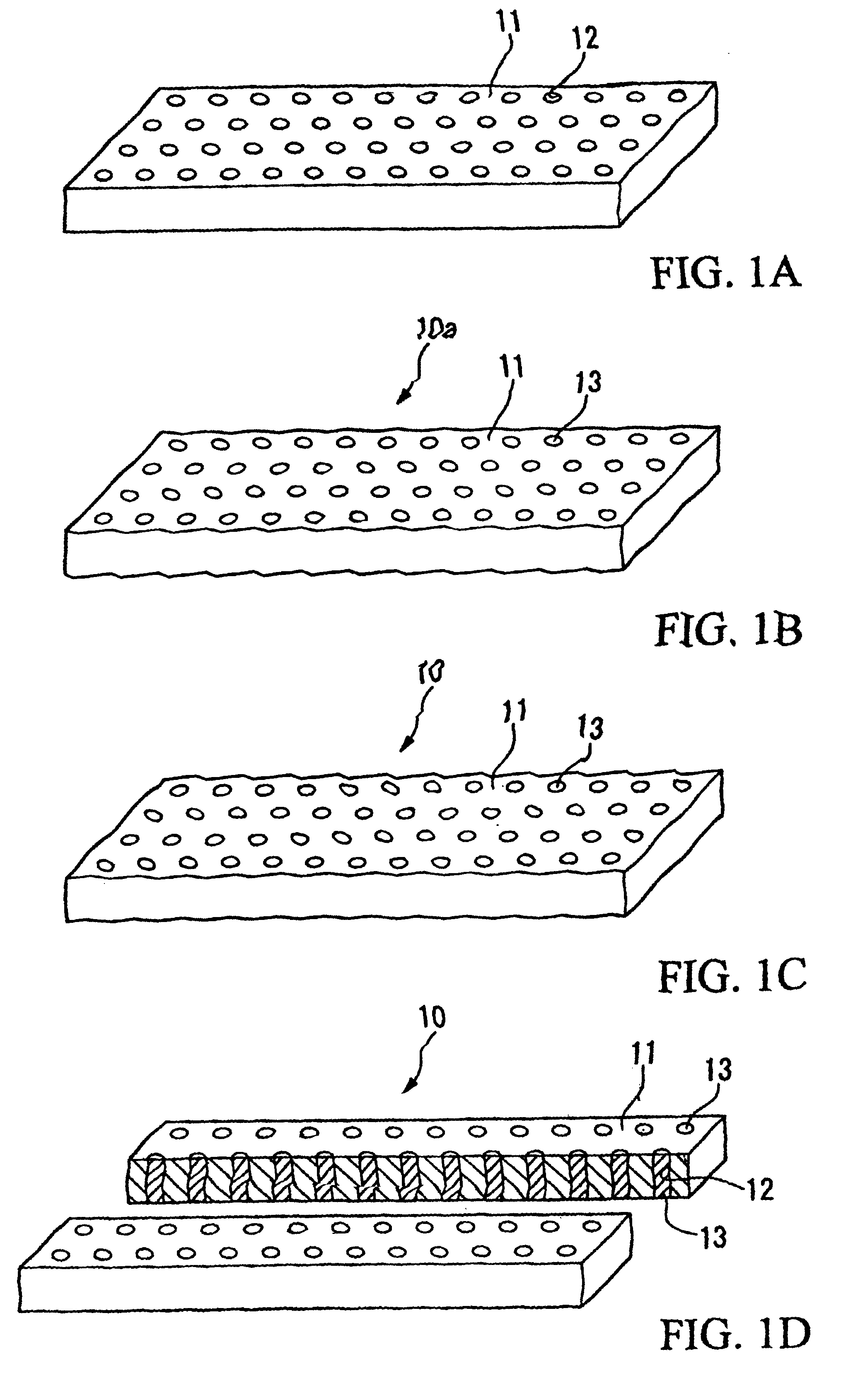
[0083]The first modified example provides a heat radiator 20 shown in FIG. 9A in which ‘rectangular’ through holes 22 (or 26) whose horizontal shape is rectangular are uniformly dispersed over the surface of a tungsten-rich base substrate 21 composed of Cu—W (or a tungsten board 25). The through holes 22 (or 26) are filled with copper-rich filler materials 23 composed of Cu—W (or copper materials 27) by infiltration. The horizontal shape of the through holes 22 (or 26) is not necessarily limited to the rectangular shape; hence, it is possible to employ other shapes such as elliptical shapes, triangular shapes, and polygonal shapes in accordance with the use of the heat radiators.

second modified example

(2) Second Modified Example

[0084]The second modified example provides a heat radiator 30 shown in FIG. 9B in which ‘circular’ through holes 32 (or 36) whose horizontal shape is circular are irregularly dispersed over the surface of a tungsten-rich base substrate 31 composed of Cu—W (or a tungsten board 35). The through holes 32 (or 36) are filled with copper-rich filler materials 33 composed of Cu—W (or copper materials 37) by infiltration. The horizontal shape of the through holes 32 (or 36) is not necessarily limited to the circular shape; hence, it is possible to employ other shapes such as elliptical shapes, rectangular shapes, and polygonal shapes in accordance with the use of the heat radiators.

third modified example

(3) Third Modified Example

[0085]The third modified example provides a heat radiator shown in FIG. 9C in which ‘linear’ through holes or channels 42 (or 46) are formed in a radial manner extending from the center to the periphery over the surface of a tungsten-rich base substrate 41 composed of Cu—W (or a tungsten board 45). Such linear through holes 42 (or 46) radially formed over the surface are filled with copper-rich filler materials 43 composed of Cu—W (or copper materials 47) by infiltration.

6. Application for Heat Radiators

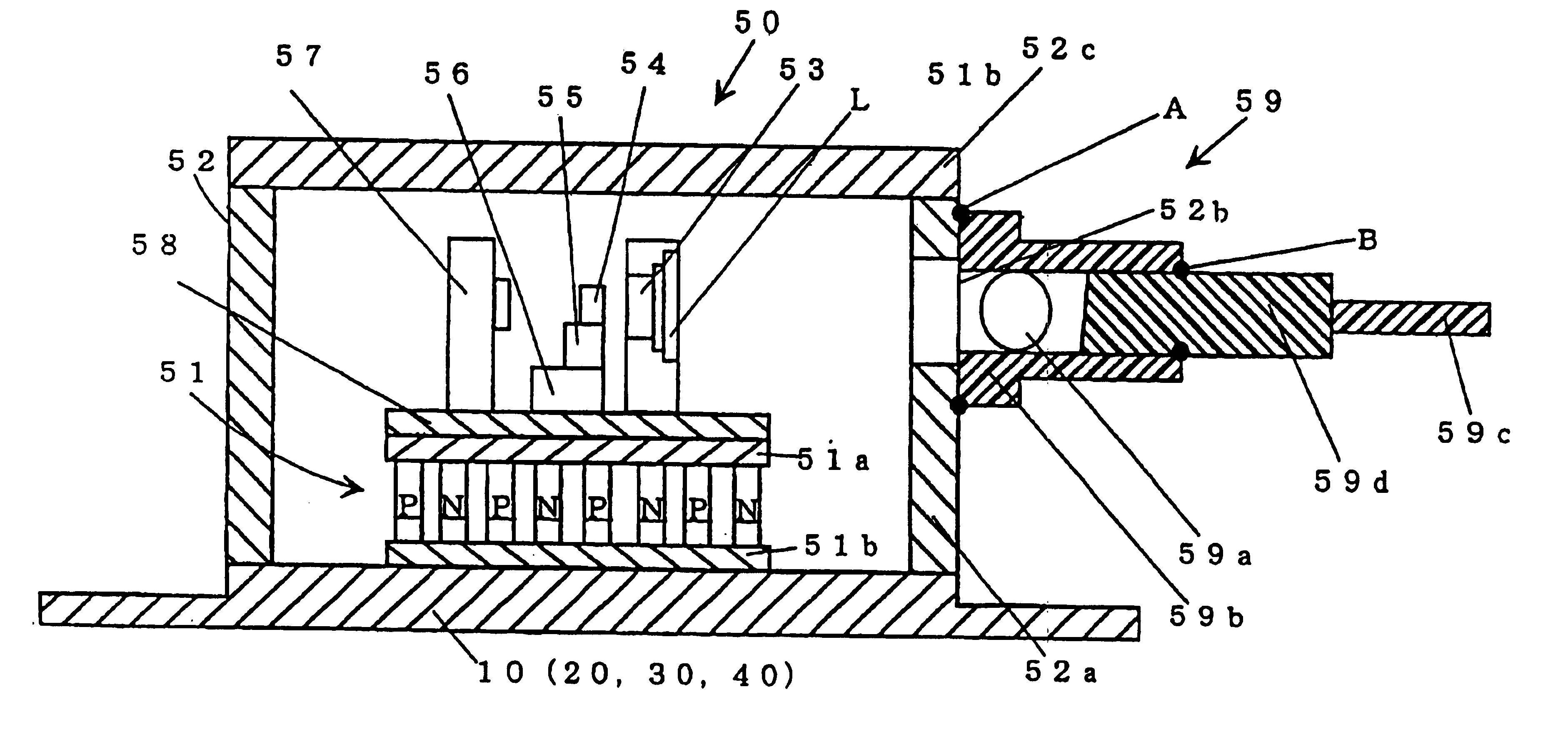
[0086]Next, an example of application for the heat radiator(s) will be described with reference to FIG. 10, which shows an internal mechanism or structure of a semiconductor laser module using heat radiators of this invention. The semiconductor laser module is constructed by integrally storing semiconductor laser elements and a lens in a package, which is connected to an optical fiber to configure an optical amplifier.

[0087]In the semiconductor laser module,...


PUM

PropertyMeasurementUnit
Temperatureaaaaaaaaaa
Diameteraaaaaaaaaa
Diameteraaaaaaaaaa

Abstract

A heat radiator for dissipating heat from an electronic device, which is mounted on a board or which is installed in a casing, to the outside thereof is basically composed of a substrate having plenty of through holes, which are produced by press molding and sintering. The substrate having a low thermal expansion coefficient is made of a copper-tungsten alloy or a copper-molybdenum alloy in which the copper content is smaller than the tungsten content or molybdenum content. The through holes each having a circular shape or a rectangular shape are infiltrated with the compound having a high thermal conductivity and composed of a copper-tungsten alloy or a copper-molybdenum alloy in which the copper content is greater than the tungsten content or molybdenum content. Thus, the heat radiator allows thermal conduction along axial directions of the through holes while substantially avoiding unwanted thermal expansion thereof.

Description

BACKGROUND OF THE INVENTION[0001]1. Field of the Invention[0002]This invention relates to heat radiators (or heatsinks) that remove heat generated by electronic devices, which include semiconductor elements mounted on substrates (or boards) or installed in casings, by heat conduction or radiation. In addition, this invention also relates to methods of manufacturing the heat radiators for dissipating heat from the electronic devices to the outside. Further, this invention relates to semiconductor laser modules in which the heat radiators are attached to bottom walls of packages for providing semiconductor laser elements.[0003]2. Description of the Related Art[0004]Advances in recent technologies bring high power outputs and high integration of electronic devices such as semiconductor elements, which may correspond to thermoelectric elements, integrated circuits (ICs), large-scale integrated circuits (LSI), very-large-scale-integrated circuits (VLSI), and diodes, for example. There is...

Claims


Application Information

Patent Timeline
IPC IPC(8): B22F7/06F28F13/00H01L21/48H01L23/373H01L23/38H01L21/02H01L23/34H01L35/00H01S5/024H01S5/00H05K7/20
CPCB22F7/06F28F13/00H01L21/4878H01L23/3733H01L23/3736H01L23/38H01L35/00H01S5/02469Y10T29/4935H01L2924/09701H01S5/02415B22F2999/00H01L2924/0002F28F2255/18B22F5/10B22F3/26H01L2924/00H10N10/00
Inventor SUZUKI, KATSUNORIIIJIMA, KENZABUROUHOSHI, TOSHIHARU
Owner YAMAHA CORP
Why Eureka
Try Eureka