

Isothermal Plate Module
- Summary
- Abstract
- Description
- Claims
- Application Information
AI Technical Summary
Benefits of technology
Problems solved by technology
Method used
Image

Examples
first embodiment
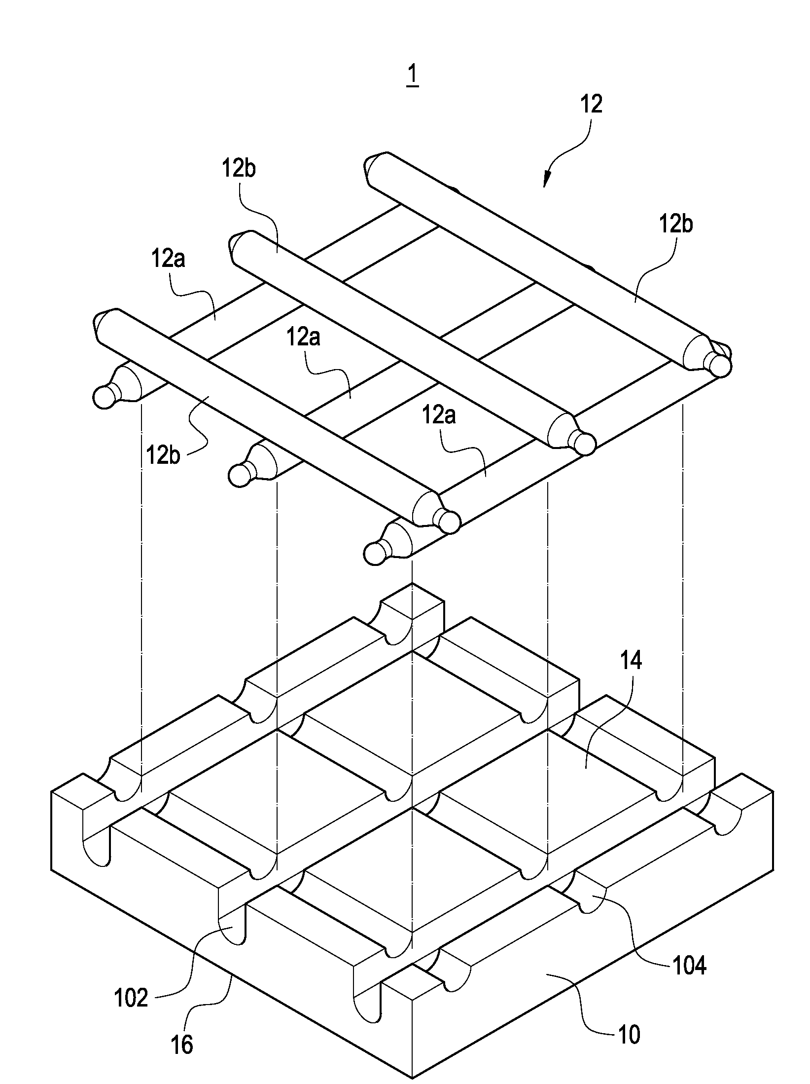
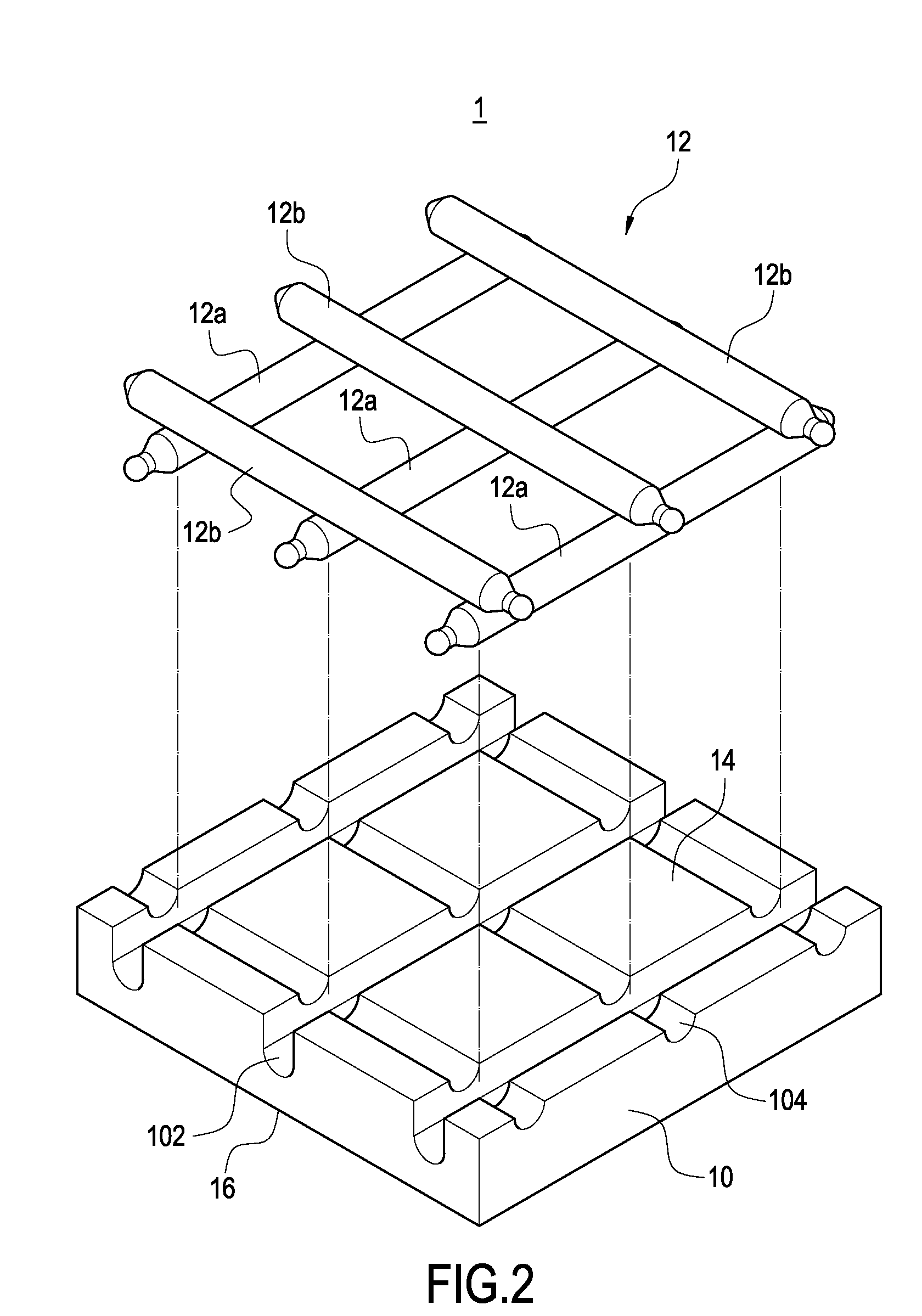
[0021]With reference to FIG. 2, it is an exploded perspective view showing the isothermal plate module of the present invention. The isothermal plate module 1 is constituted of an isothermal plate body 10 and a plurality of heat pipes 12. The isothermal plate body 10 has first recesses 102 extending along a first direction and second recesses 104 extending along a second direction. In this figure, the first or second recesses 102, 104 are parallel to one another to form a space between any parallel first or second recess. The first recesses 102 and the second recesses 104 are staggered and overlapped with one another, so that the end face 14 of the isothermal plate body 10 is formed into a mesh-like arrangement. Each first recess 102 is formed into a deeper recess, so that the heat pipes 12a having the same orientation can be completely disposed in the isothermal plate body 10. Each second recess 104 has a level difference with respect to the first recess 102, so that the heat pipes...
second embodiment
[0024]With reference to FIG. 5 and FIG. 6, the present invention will be described. In the present embodiment, it aims to produce a heat source device having a large area. As shown in the previous embodiment, the recesses 102, 104 of the present invention can be achieved by processing on the end face 14 of the isothermal plate body 10. Therefore, no matter the area of the isothermal plate is large or not, the same processing procedure can be applied. Therefore, in the present embodiment, it is not difficult to form the first recesses 102′ along the first direction and second recesses 104′ along the second direction on the isothermal plate body 10′ having a large area. Further, the heat pipes 12a′, 12b′ can be made to have a length identical to the length or width of the isothermal plate.
[0025]The present invention can be applied to the electronic apparatuses having a high density of heat generation. FIG. 6 shows the isothermal plate module 1′ of the second embodiment, in which a sim...
third embodiment
[0027]FIG. 8 is a cross-sectional side view of the third embodiment shown in FIG. 7. It is well known that the heat pipe 12c includes a sealing end 122 (exemplified by the designated heat pipe 12c). The wall face formed by the sealing end 122 shrinks to form a thickness and thus is not a flat end. Therefore, if each third recess 106 provided in the third direction is a blind hole, the sealing end 122 of the heat pipe 12c can be ground in advance, so that the wall face can be formed into a substantially flat surface. In this way, a larger contacting area can be formed between the sealing end 122 of the heat pipe 12c and the bottom of the recess 106. If each third recess 106 is a through hole, in addition to the above grinding process, all the heat pipes 12c can be firstly disposed on the third recess 106. Then, all the sealing ends 122 exposed from the through hole are ground in one time. The thus-ground heat pipes 12c and the end surface are coated with a heat-conducting glue, there...
PUM
 Abstract
Description
Claims
Application Information