Heat exchanger

a heat exchanger and heat exchanger technology, applied in the direction of heat exchanger fastening, lighting and heating apparatus, stationary conduit assemblies, etc., can solve the problems of difficult to apply uniform compression force, disadvantageously impossible to sufficiently secure the sealing performance, etc., to achieve uniform thickness, uniform thickness, uniform thickness

Active Publication Date: 2011-07-14
DENSO CORP
View PDF8 Cites 26 Cited by
  • Summary
  • Abstract
  • Description
  • Claims
  • Application Information

AI Technical Summary

Benefits of technology

In order to achieve the objective of the present invention, there is provided a heat exchanger that includes a core unit and a pair of header tanks. The core unit has a plurality of tubes that allows fluid to circulate therethrough. The pair of header tanks is positioned at longitudinal end portions of the plurality of tubes. The pair of header tanks extends in a direction orthogonal to a longitudinal direction of the tubes to be communicated with the plurality of tubes. Each of the pair of header tanks has a core plate, to which the tubes are bonded, and a tank main body, which together with the core plate defines a tank space. The tank main body has at least a first main body segment and a second main body segment. The header tank is provided with partitioning means that divides the header tank into a first space, which is an internal space of the first main body segment, and a second space, which is an internal space of the second main body segment, such that at least the first space and the second space are arranged in a longitudinal direction of the header tank. The partitioning means has a first partitioning surface that faces the first space and has a second partitioning surface that faces the second space. A plurality of heat exchanger units is defined by dividing the core unit at the partitioning means in a direction, in which the first space and the second space are arranged. The core plate has a tube bonding surface, to which the tubes are bonded. The tube bonding surface has an annular outer peripheral seal surface formed therearound over an entire perimeter of the tube bonding surface. A seal member, which seals between the core plate and an end portion of the tank main body adjacent the core plate, is provided in the annular outer peripheral seal surface. The tube bonding surface has a partitioning seal surface at a position, which corresponds to the partitioning means. The seal member is provided at the partitioning seal surface to seal between the core plate and the partitioning means. The partitioning seal surface is positioned on a plane that is identical with a plane of the outer peripheral seal surface. The seal member has a part, which is held by the core plate and the tank main body therebetween, and which has a uniform thickness.
In order to achieve the objective of the present invention, there is also provided a heat exchanger that includes a core unit, a pair of header tanks, a partition wall, and a plurality of heat exchanger units. The core unit has a plurality of tubes that allows fluid to circulate therethrough. The pair of header tanks is provided at longitudinal end portions of the plurality of tubes. The pair of header tanks extends in a direction orthogonal to a longitudinal direction of the tubes to be communicated with the plurality of tubes. Each of the pair of header tanks has a core plate, to which the tubes are bonded, and a tank main body, which together with the core plate defines a tank space. The partition wall is provided within the header tank. The partition wall has a plate shape and divides the tank space into at least a first space and a second space. The first space and the second space are arranged in a longitudinal direction of the header tank. The plurality of heat exchanger units is defined by dividing the core unit at the partition wall in a direction, in which the first space and the second space are arranged. The core plate has a tube bonding surface, to which the tubes are bonded. The tube bonding surface has an annular outer peripheral seal surface formed therearound over an entire perimeter of the tube bonding surface. A seal member, which seals between the core plate and an end portion of the tank main body adjacent the core plate, is provided at the annular outer peripheral seal surface. The tube bonding surface has a partitioning seal surface at a position, which corresponds to the partition wall. The seal member is provided at the partitioning seal surface to seal between the core plate and the partition wall. The partitioning seal surface is positioned on a plane that is identical with a plane of the outer peripheral seal surface. The seal member has a part, which is held by the core plate and the tank main body therebetween, and which has a uniform thickness.
In order to achieve the objective of the present invention, there is also provided with a heat exchanger that includes a first core unit, a second core unit, a core plate, a first main body segment, a second main body segment, a seal member, and partitioning means. The first core unit has a plurality of first tubes that allows first fluid to flow therethrough. The second core unit has a plurality of second tubes that allows second fluid to flow therethrough. The core plate is connected with longitudinal end portions of the first tubes and the second tubes. The first main body segment is bonded to the core plate. The first main body segment extends in a direction orthogonal to a longitudinal direction of the first tubes such that the first main body segment defines a first space that is communicated with the first tubes. The second main body segment is bonded to the core plate. The second main body segment extends in a direction orthogonal to a longitudinal direction of the second tubes such that the second main body segment defines a second space that is communicated with the second tubes. The seal member seals between the core plate and the first main body segment and seals between the core plate and the second main body segment. The first space and the second space are arranged in the direction orthogonal to the longitudinal direction of the first tubes and the second tubes. The partitioning means separates the first space from the second space. The seal member seals between the core plate and one of the first main body segment, the second main body segment, and the partitioning means. The core plate includes a tube bonding surface, an annular outer peripheral seal surface, and a partitioning seal surface. The tube bonding surface has insert bores, into which the first and second tubes are inserted. The annular outer peripheral seal surface is formed around the tube bonding surface and is provided with the seal member. The partitioning seal surface is formed at a position opposed to an end portion of the partitioning means, and is provided with the seal member. The partitioning seal surface is positioned on a plane that is identical with a plane of the outer peripheral seal surface. The seal member has a part, which is held by the core plate and the one of the first main body segment, the second main body segment, the partitioning means therebetween, and which has a uniform thickness.

Problems solved by technology

However, because the seal surface has the curved shape, it is difficult to apply the uniform compression force to the entirety of the seal surface, and thereby it is difficult to sufficiently secure the sealing performance.
Also, in the heat exchanger of JP-A-2003-336994, because the gasket is eliminated, it is disadvantageously impossible to sufficiently secure the sealing performance.

Method used


Image

  • Heat exchanger
  • Heat exchanger
  • Heat exchanger

Examples


first embodiment

The first embodiment of the present invention will be described below with reference to FIGS. 1 to 9. The present embodiment describes an example of a case, where a heat exchanger according to the present invention is applied to a heat exchanger for a hybrid vehicle, in which a traveling drive force is obtained based on an engine and a driving electric motor.

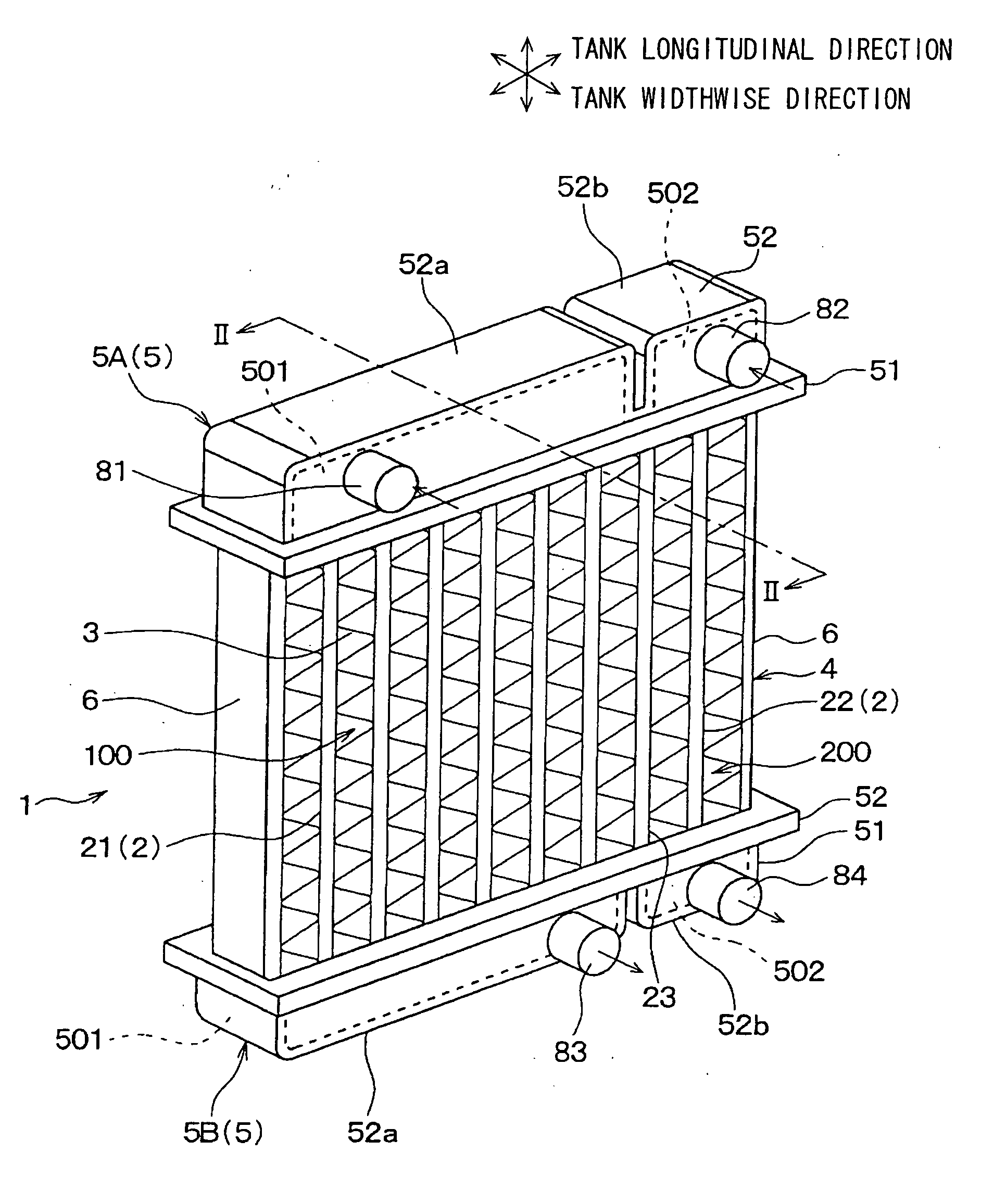
FIG. 1 is a perspective view illustrating a heat exchanger 1 of the first embodiment. As shown in FIG. 1, the heat exchanger 1 of the present embodiment has a core unit 4 and a pair of header tanks 5. The core unit 4 includes multiple tubes 2 and fins 3, and the pair of header tanks 5 is assembled on both end portions of the core unit 4.

The tubes 2 allow fluid to flow therethrough, and the tube 2 is formed to have a flat shape such that a direction of a longitudinal diameter of the tube 2 coincides with an air flow direction. Also, the multiple tubes 2 are arranged in parallel with each other in a horizontal direction such that ...

second embodiment

Next, the second embodiment of the present invention will be described with reference to FIG. 10. FIG. 10 is an enlarged sectional view illustrating a vicinity of dummy tubes 23 of a heat exchanger 1 according to the present second embodiment. As shown in FIG. 10, the partitioning seal surface 517 of the core plate 51 does not include holes, into which the dummy tubes 23 are inserted. Due to the above, the dummy tubes 23 remain not-inserted into the core plate 51, and thereby there is a clearance formed between the core plate 51 and a longitudinal end portion of the dummy tube 23. It should be noted that although there are two dummy tubes 23 in the present embodiment, there may be only one dummy tube 23. Also, there maybe three or more dummy tubes 23.

Also, conventionally, at a bonding part between the core plate 51 and the dummy tube 23, residue of blazing may damage the partitioning seal surface 517 of the core plate 51, and thereby degrading sealing performance of sealing between ...

third embodiment

Next, the third embodiment of the present invention will be described with reference to FIGS. 11 to 14. FIG. 11 is a perspective view illustrating a heat exchanger 1 of the present third embodiment, FIG. 12 is a cross-sectional view taken along a line XII-XII in FIG. 11, FIG. 13 is an exploded perspective view illustrating a header tank 5 of the heat exchanger 1 of the present third embodiment, and FIG. 14 is an exploded perspective view illustrating a main part in FIG. 13.

As shown in FIGS. 11 to 14, in the heat exchanger 1 of the present embodiment, two partition walls 7 are provided within the header tank 5 at a boundary between the first radiator unit 100 and the second radiator unit 200 in order to divide the in-tank space in a tube longitudinal direction. In other words, the two partition walls 7 are provided between the first tubes 21 and the second tubes 22. Also, the two partition walls 7 are arranged at predetermined intervals. Due to the above, the in-tank space within the...


PUM


Abstract

A heat exchanger has partitioning means for dividing a header tank such that a first space and a second space of a tank main body are arranged in a longitudinal direction of the header tank. An annular outer peripheral seal surface is provided around a tube bonding surface of a core plate of the header tank over an entire perimeter thereof and is provided with a gasket. A partitioning seal surface is provided to the tube bonding surface at a position corresponding to the partitioning means, and is provided with the gasket. The gasket seals between the core plate and the partitioning means. The partitioning seal surface is positioned on a plane identical with a plane of the outer peripheral seal surface. A part of the gasket, which is held by the core plate and the tank main body therebetween, has a uniform thickness.

Description

CROSS REFERENCE TO RELATED APPLICATIONThis application is based on and incorporates herein by reference Japanese Patent Application No. 2009-254941 filed on Nov. 6, 2009BACKGROUND OF THE INVENTION1. Field of the InventionThe present invention relates to a heat exchanger having multiple heat exchanger units that are integrally formed.2. Description of Related ArtConventionally, JP-A-2002-115991 (corresponding to US2002 / 0040776) discloses a heat exchanger, which has multiple tubes allowing fluid to flow therethrough, and which has a header tank provided at longitudinal end portions of the tubes to be communicated with the tubes. Multiple heat exchanger units are integrally formed by partitioning an internal space of the header tank by partition walls (separators).In the heat exchanger of JP-A-2002-115991, the header tank includes a core plate and a tank main body. The core plate has tube insertion bores, into which the tubes are inserted in a bonded manner. The tank main body, togethe...

Claims


Application Information

Patent Timeline
Patent Type & Authority Applications(United States)
IPC IPC(8): F28F9/02
CPCF28D1/0443F28F9/0209F28F2270/02F28F2275/122F28F2230/00F28F9/0226
Inventor TAKAHASHI, EIZOUKIMATA, MITSURUYAMANAKA, AKIRANAKAMURA, MASAYAMIZUNO, YASUHIRO
Owner DENSO CORP
Why Eureka
Try Eureka