Shaft brake mechanism of wind power generator

a technology of shaft brake and wind power generator, which is applied in the direction of braking disc, electric generator control, braking system, etc., can solve the problems of large electrical energy consumed for maintaining, reduced total power generation capacity of wind power generator, and increased maintenance costs. , to achieve the effect of energy saving

Inactive Publication Date: 2011-07-14
HIWIN MIKROSYST
View PDF27 Cites 36 Cited by
  • Summary
  • Abstract
  • Description
  • Claims
  • Application Information

AI Technical Summary

Benefits of technology

[0004]It is therefore a primary object of the present invention to provide a shaft brake mechanism of wind power generator, in which the electrical power for providing braking effect for the shaft is much less than that of the conventional device. Therefore, the shaft brake mechanism of the present invention has energy-saving effect.
[0005]It is a further object of the present invention to provide the above shaft brake mechanism of wind power generator, in which a smaller force is input to create a greater output force for providing braking effect for the shaft. Therefore, the shaft brake mechanism of the present invention has power-saving effect.
[0006]It is still a further object of the present invention to provide the above shaft brake mechanism of wind power generator, which can naturally restrain the rotational speed of the shaft from proportionally increasing with the wind speed. Therefore, the wind power generator can still safely operate in a condition that the wind speed exceeds a nominal upper limit of wind speed. Accordingly, without modifying the nominal upper limit of rotational speed, the nominal upper limit of wind speed can increase to increase total power generation capacity.

Problems solved by technology

As a result, a large amount of electrical energy is consumed for maintaining the function of such electromagnetic brake system.
Moreover, as shown in FIG. 10A, when a wind power generator operates in a condition that the rotational speed exceeds a nominal upper limit t1, the safety in operation will be threatened.
In this case, the total power generation capacity of the wind power generator will be reduced and the natural wind power resource can be hardly fully utilized to cause waste of resource.

Method used


Image

  • Shaft brake mechanism of wind power generator
  • Shaft brake mechanism of wind power generator
  • Shaft brake mechanism of wind power generator

Examples


Embodiment Construction

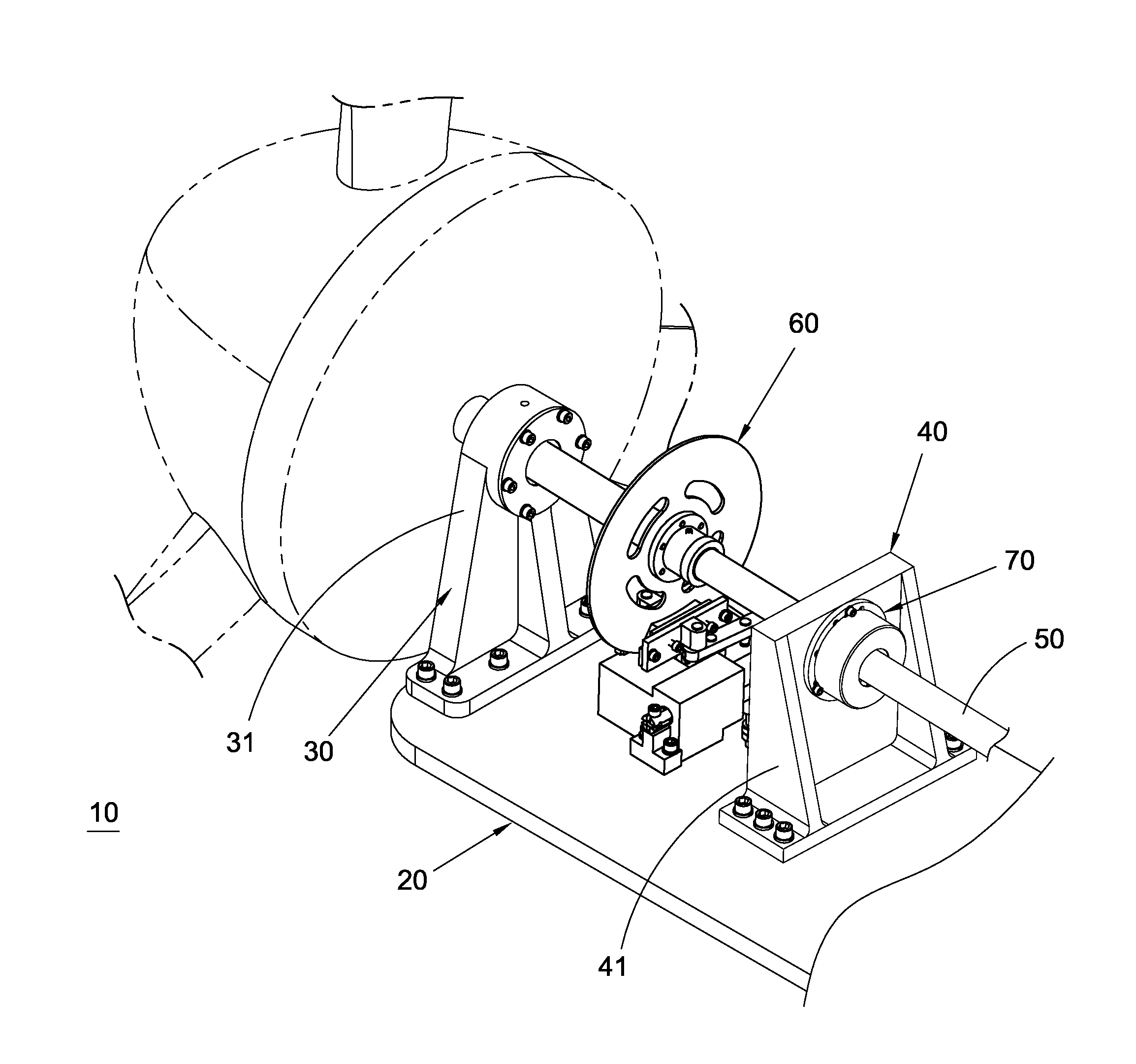
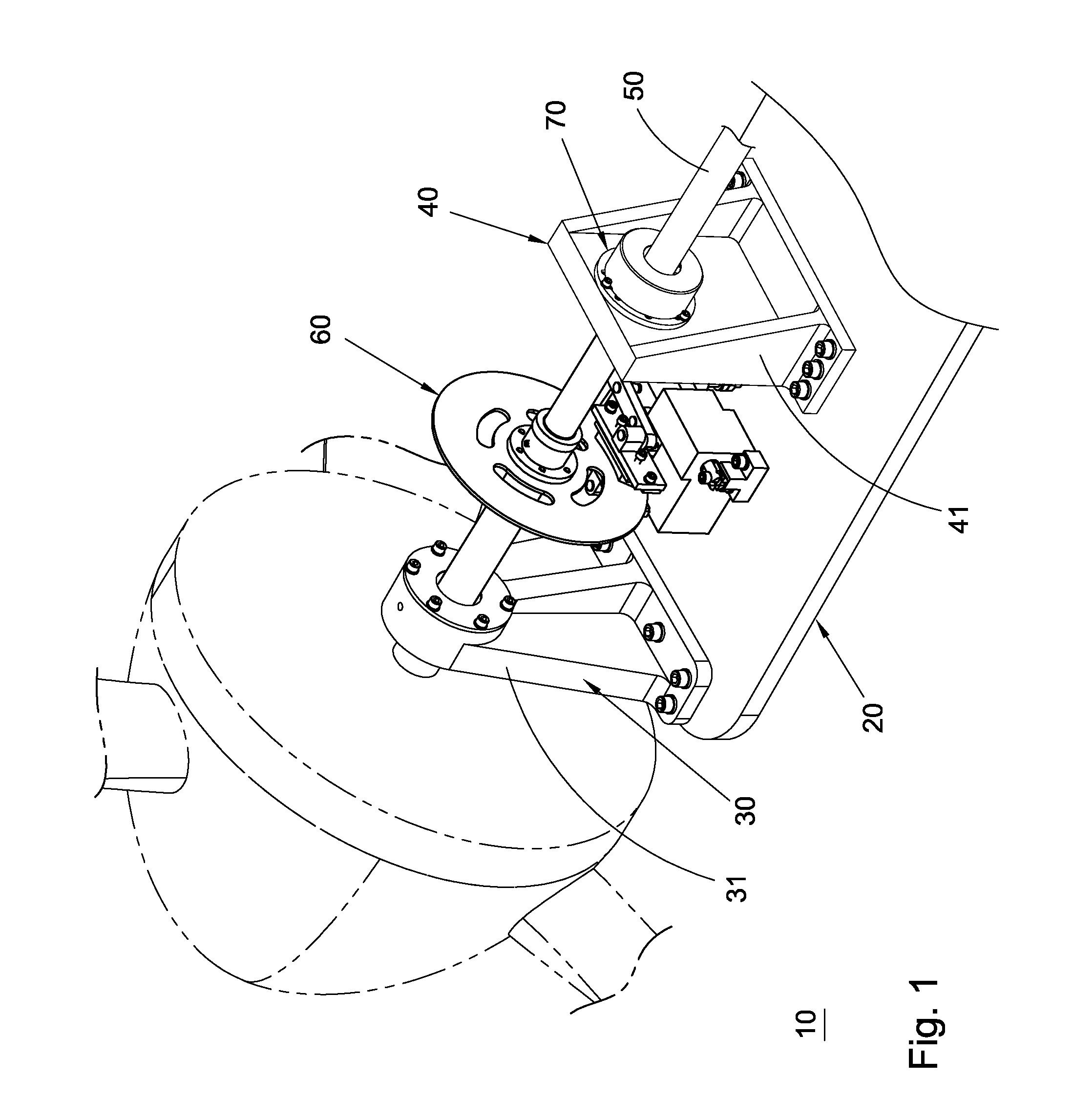
[0021]Please refer to FIGS. 1 to 9. According to a preferred embodiment, the shaft brake mechanism 10 of wind power generator of the present invention includes a board-like bed 20, a first pier 30, a second pier 40, a shaft 50, a first brake assembly 60 and a second brake assembly 70.

[0022]The piers 30, 40 are side by side disposed on the bed 20. Each of the piers 30, 40 has an upright plate-like seat body 31, 41 in which a bearing is inlaid. The bearings of the piers 30, 40 have central shaft holes, which are coaxially aligned with each other.

[0023]The shaft 50 is rotatably fitted through the shaft holes of the bearings and bridged between the piers 30, 40.

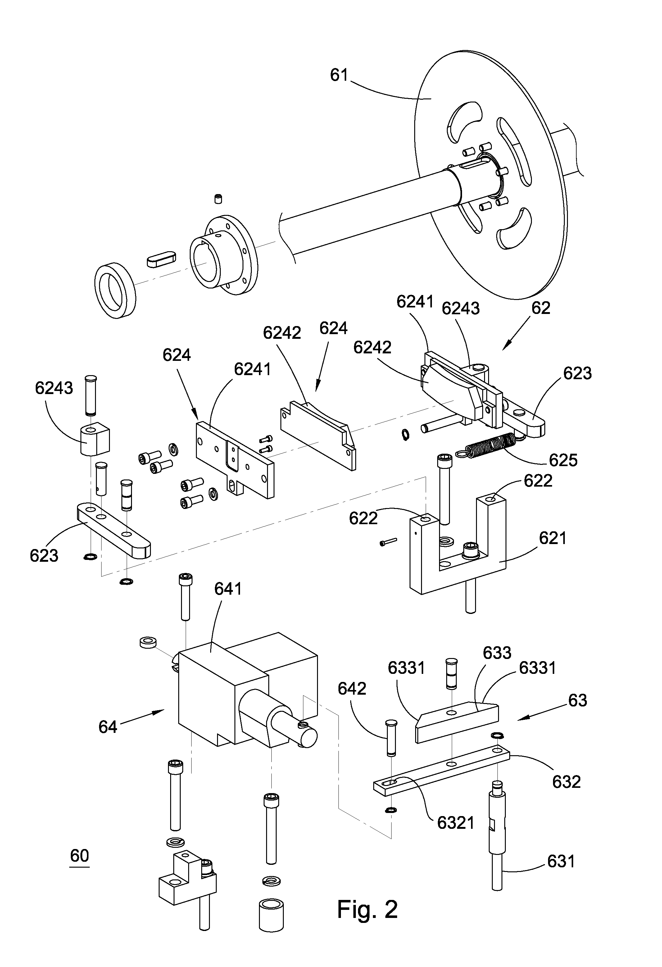
[0024]The first brake assembly 60 provides braking effect for the shaft 50 by means of disc brake technique. The first brake assembly 60 includes an annular disc 61 coaxially fixedly fitted around the shaft 50 between the piers 30, 40. The disc 61 is rotatable with the shaft 50. The first brake assembly 60 further includes a clam...


PUM


Abstract

A shaft brake mechanism of wind power generator, including a first brake assembly and a second brake assembly independent from each other. The first brake assembly serves to provide braking effect for the shaft of the wind power generator against rotation. The second brake assembly serves to naturally restrain the rotational speed of the shaft from exceeding a nominal upper limit of rotational speed. Accordingly, the wind power generator can still safely operate in a situation that the wind speed exceeds a nominal upper limit of wind speed. Therefore, the wind speed range for the operation of the wind power generator is widened to increase the total power generation capacity thereof.

Description

BACKGROUND OF THE INVENTION[0001]The present invention relates generally to wind power generation, and more particularly to a shaft brake mechanism of wind power generator.[0002]In wind power generation, as the wind blows, the blades are driven to make the shaft of the generator rotate for converting kinetic energy into electrical energy. However, it is necessary to brake the shaft against rotation in some situations. Conventionally, an electromagnetic brake system is generally used to provide braking effect for the shaft. Such electromagnetic brake system must be continuously powered to keep providing braking effect or stop providing braking effect, allowing the shaft to rotate. As a result, a large amount of electrical energy is consumed for maintaining the function of such electromagnetic brake system.[0003]Moreover, as shown in FIG. 10A, when a wind power generator operates in a condition that the rotational speed exceeds a nominal upper limit t1, the safety in operation will be...

Claims


Application Information

Patent Timeline
Patent Type & Authority Applications(United States)
IPC IPC(8): F03D9/00F16D65/12
CPCF03D7/0248F05B2260/902F16D51/40F16D55/2245Y02E10/725F16D2125/66F16D2127/002Y02E10/723F16D2125/64Y02E10/72
Inventor WEI, JHEN-YOUTSAI, KUO-YUANCHEN, EN-FENGHUANG, TZU-YAO
Owner HIWIN MIKROSYST
Why Eureka
Try Eureka