Reflector for a lighting assembly

a technology for reflecting devices and lighting components, applied in lighting applications, lighting and heating devices, instruments, etc., can solve the problems of not being able to disclose the configuration of the housing, the installation can be very time-consuming, and the associated costs can be substantial, so as to save costs, improve the glow, and light more efficiently

Active Publication Date: 2011-07-14
BEST LIGHTS
View PDF34 Cites 69 Cited by
  • Summary
  • Abstract
  • Description
  • Claims
  • Application Information

AI Technical Summary

Benefits of technology

The present invention provides a lighting assembly utilizing a reflective body for use with a light source to disperse light from the light source. The reflective body includes a lower array of first reflectors arranged about a central axis. Each of the first reflectors form an obtuse angle with the next adjacent first reflector. The reflective body also includes an upper array of second reflectors arranged about the central axis. Each of said second reflectors include a left face and a right face. The upper array defines obtuse angles between next adjacent second reflectors. Additionally, reflex angles are defined between the left and right faces of the second reflectors. The combination of angles evenly disperse the light supplied from the light source to provide a improved glow. The lighting assembly of the present invention also provides for ease of installation, since typical facilities require numerous assemblies. Additionally, the lighting assemblies of the present invention do not require any specialized wiring to be done by the end user, i.e. saving the cost of an electrician or a specialized technician. The lighting assembly of the present invention need only be plugged into a standard electrical outlet. Further the lighting assembly of the present invention emits light more efficiently than the lighting assemblies currently known in the art.

Problems solved by technology

Typically there are multiple lights required to light the area, therefore installation can be very time consuming and the associated costs can be substantial.
These patents fail to disclose a housing that is configured to accept all of the electrical components within the housing.
As stated above, the lighting assemblies disclosed in the prior art typically require an electrician or other type of specialized technician to properly install and wire these assemblies which can prove to be difficult near the ceiling, so far off the ground.
Typically, lighting assemblies are less than 90% efficient, i.e. the assemblies emit less than 90% of the light output from the light source.

Method used


Image

  • Reflector for a lighting assembly
  • Reflector for a lighting assembly
  • Reflector for a lighting assembly

Examples


Embodiment Construction

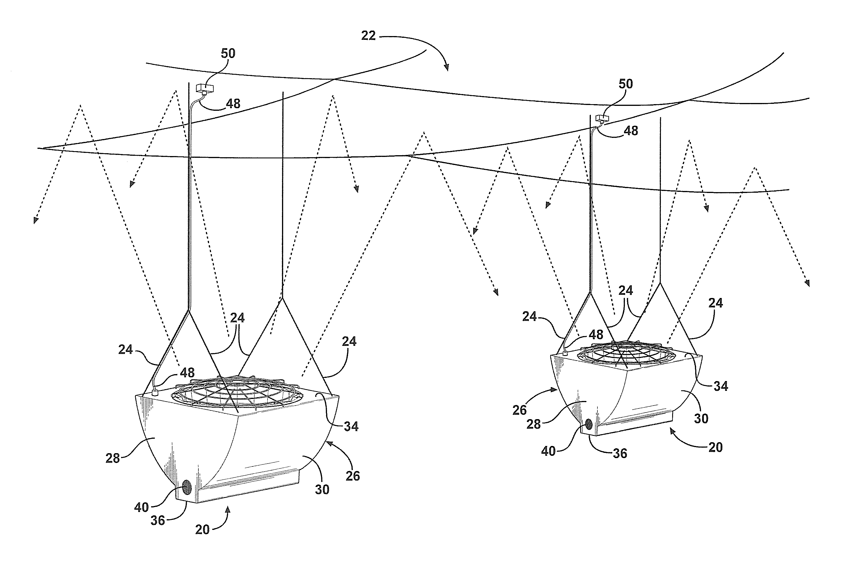
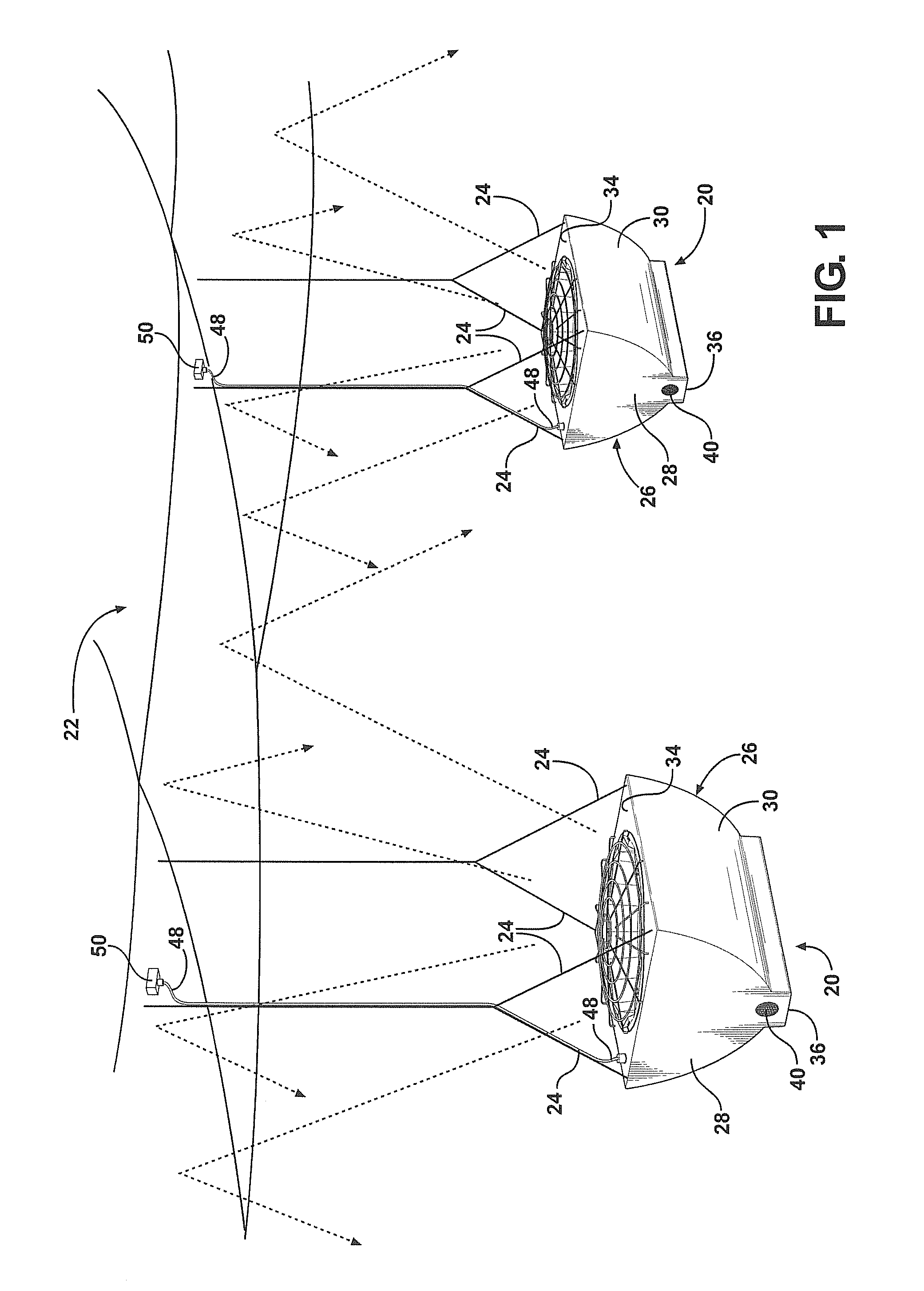
Referring to the Figures wherein like numerals indicate like or corresponding parts throughout the several views, a lighting assembly is generally shown at 20.

As best shown in FIG. 1, the lighting assembly 20 provides light for indoor facilities, such as sporting arenas and pool areas. Each lighting assembly 20 is suspended from a ceiling 22 of the indoor facilities and illuminates the ceiling 22 thereby providing indirect light to an area (not shown) below the lighting assembly 20. Hence, such assemblies are typically referred to as indirect-light assemblies. For illustrative purposes, light rays are shown with dashed lines in FIG. 1. Typically, a plurality of cables 24 are used to suspend the lighting assembly 20 from the ceiling 22. However it should be appreciated that any suitable method of coupling the lighting assembly 20 to the ceiling 22 may be employed without deviating from the subject invention.

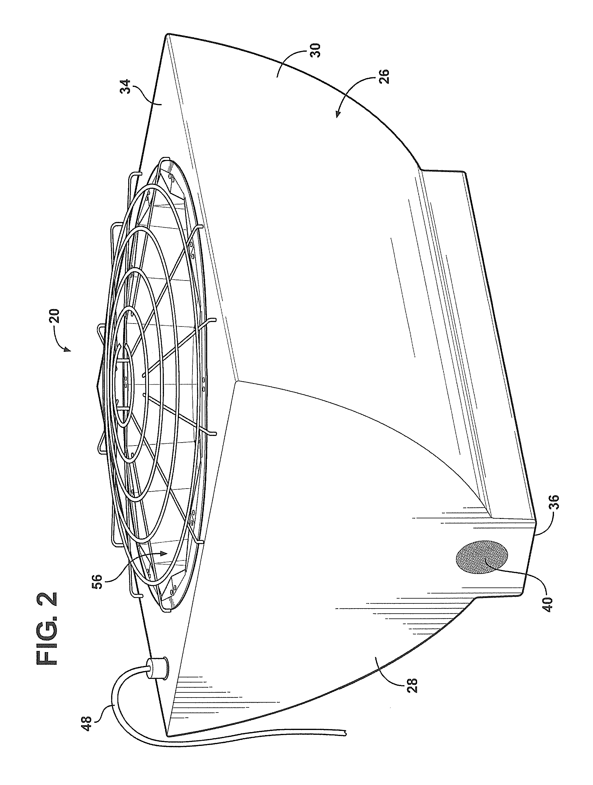
Referring additionally to FIGS. 2-5, the lighting assembly 20 includes a hous...


PUM


Abstract

A lighting assembly utilizing a reflective body for use with a light source to uniformly disperse the light from the light source. The reflective body includes a lower array of first reflectors arranged about a central axis. Each of the first reflectors form an obtuse angle with the next adjacent first reflector. The reflective body also includes an upper array of second reflectors arranged about the central axis. Each of said second reflectors include a left face and a right face. The upper array defines obtuse angles between next adjacent second reflectors. Additionally, reflex angles are defined between the left and right faces of the second reflectors. The combination of angles evenly disperse the light supplied from the light source to provide a pleasant glow for illuminating an area below the lighting assembly without causing hot spots.

Description

FIELD OF THE INVENTIONThe present invention generally relates to an indirect lighting assembly, and more specifically, to a reflective body for dispersing light out of the lighting assembly and to a surface above the lighting assembly and reflected to an area below the lighting assembly to produce uniform indirect illumination to the area below.BACKGROUNDVarious lighting assemblies utilizing reflectors are well known in the prior art. Many on the lighting assemblies of the prior art include reflectors in an attempt to optimize the amount of light output. One such assembly, used for industrial lighting, utilizes a dome-shaped reflector formed of vertically oriented faces arranged around an axis. Each of the faces extend from the top to the bottom of the dome and are symmetrically arranged side-by-side for defining a plurality of vertically oriented ridges and grooves to provide overlapping areas of light to the area below the light assembly. Additionally, each of the faces have a con...

Claims


Application Information

Patent Timeline
Patent Type & Authority Applications(United States)
IPC IPC(8): H01J61/52F21V7/00H05B41/36
CPCF21S8/061F21V7/0008F21V7/048F21W2131/407F21V15/02F21W2131/10F21W2131/401F21V7/10
Inventor YURICH, GARY D.
Owner BEST LIGHTS
Why Eureka
Try Eureka