
Lateral wave radar system for forward detection

a radar system and lateral wave technology, applied in the field of radar detection, can solve the problems of not being able to reliably detect buried objects close to the front of a moving vehicle or to detect at a significant distance, being bulky, and showing very limited success according to the published results, and achieving the effect of limited success

Inactive Publication Date: 2011-07-14
THE OHIO STATE UNIV RES FOUND
View PDF13 Cites 17 Cited by
  • Summary
  • Abstract
  • Description
  • Claims
  • Application Information

AI Technical Summary

Benefits of technology

"The patent text discusses the use of forward-looking radar to detect buried objects. However, current radar systems have limitations in detecting objects close to the front of a moving vehicle or at a significant distance. The text also explains the behavior of ground waves and lateral waves in detecting buried objects and how the presence of ground can modify the antenna's radiation patterns. The technical effect of the patent text is to provide a better understanding of the physical mechanisms involved in detecting buried objects and to improve the reliability and accuracy of forward-looking radar systems."

Problems solved by technology

Although downward-looking ground penetrating radars have been developed for detecting buried objects, they are not able to reliably detect buried objects close to the front of a moving vehicle or to detect the at a significant distance.
It was bulky and showed very limited success according published results.
For a slightly deeper target, this configuration becomes much less effective.
Furthermore, roads in urban areas often contain multiple layers of pavements that may significantly affect the behavior incident and scattered fields.
On the other hand, detecting a deeper target away from the layer may become ineffective.
However, if the layer thickness less than one wavelength, it forms a leaky waveguide that serves to guide energy both inside and outside of the layer.
However, there is a lack of physical interpretation about actual wave mechanisms involved as no commercial embodiments employing lateral waves were developed.
However, in most subsurface sensing applications, the above far-field expressions are not applicable since most targets of interest are not in the far field and the medium is not simple.

Method used


Image

  • Lateral wave radar system for forward detection
  • Lateral wave radar system for forward detection
  • Lateral wave radar system for forward detection

Examples


Embodiment Construction

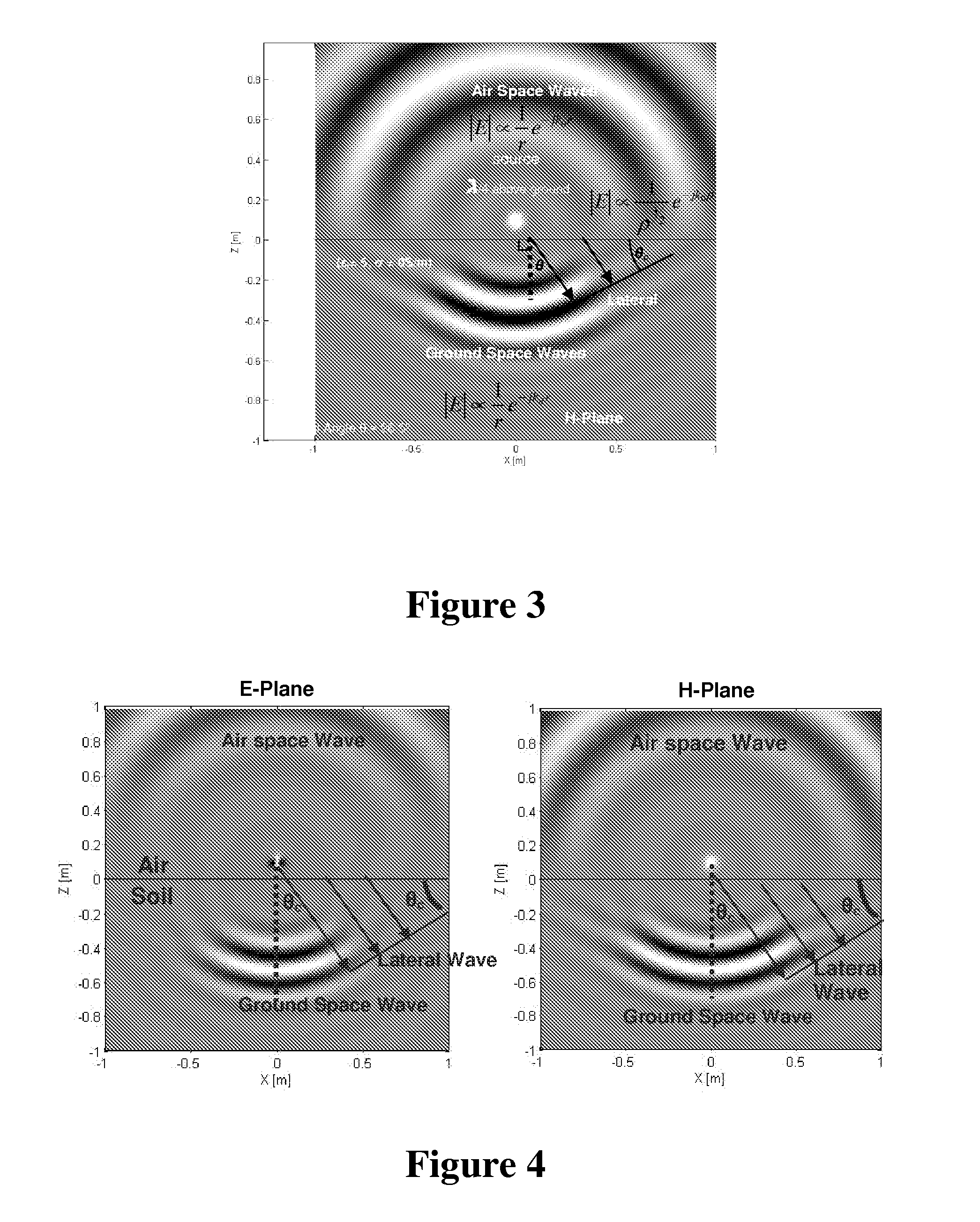
[0096]The radiation power and radiation pattern from a small dipole located on or near ground surface were examined. FIG. 9 shows the calculated far-field radiation patterns at 100 MHz for a short dipole antenna positioned at different antenna heights above a ground characterized by εr=5 and σ=0 S / m. Below the ground, ground waves dominate radiation within a solid cone angle defined by the critical angle (θc=26.5°). Radiation beyond the critical angle is dominated by lateral waves. These results reveal that elevating an antenna's height causes reduction in lateral wave excitations and results in radiation mainly confined within the solid cone. This finding suggests that the antenna height should be kept less than 1 / 10 of wavelength in order to excite strong lateral waves.

[0097]It is a well know phenomenon in ground penetrating radar applications that more electromagnetic energy is coupled into ground when the antenna is close to ground. This phenomenon can be quantitatively describe...


PUM


Abstract

A forward-looking radar system adapted to detect and identify buried or near surface objects from a moving ground vehicle has been developed. The system incorporates a radar detection system and in one embodiment is mounted on a ground vehicle. The system is adapted to differentiate common roadway clutter from objects of interest.

Description

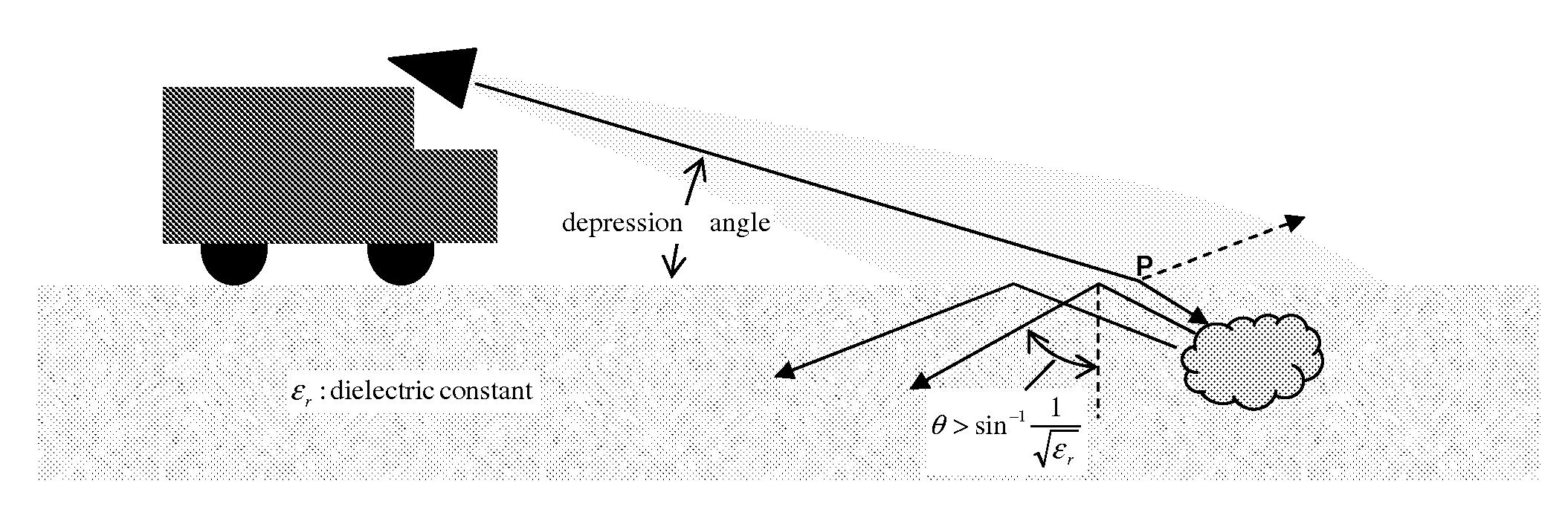
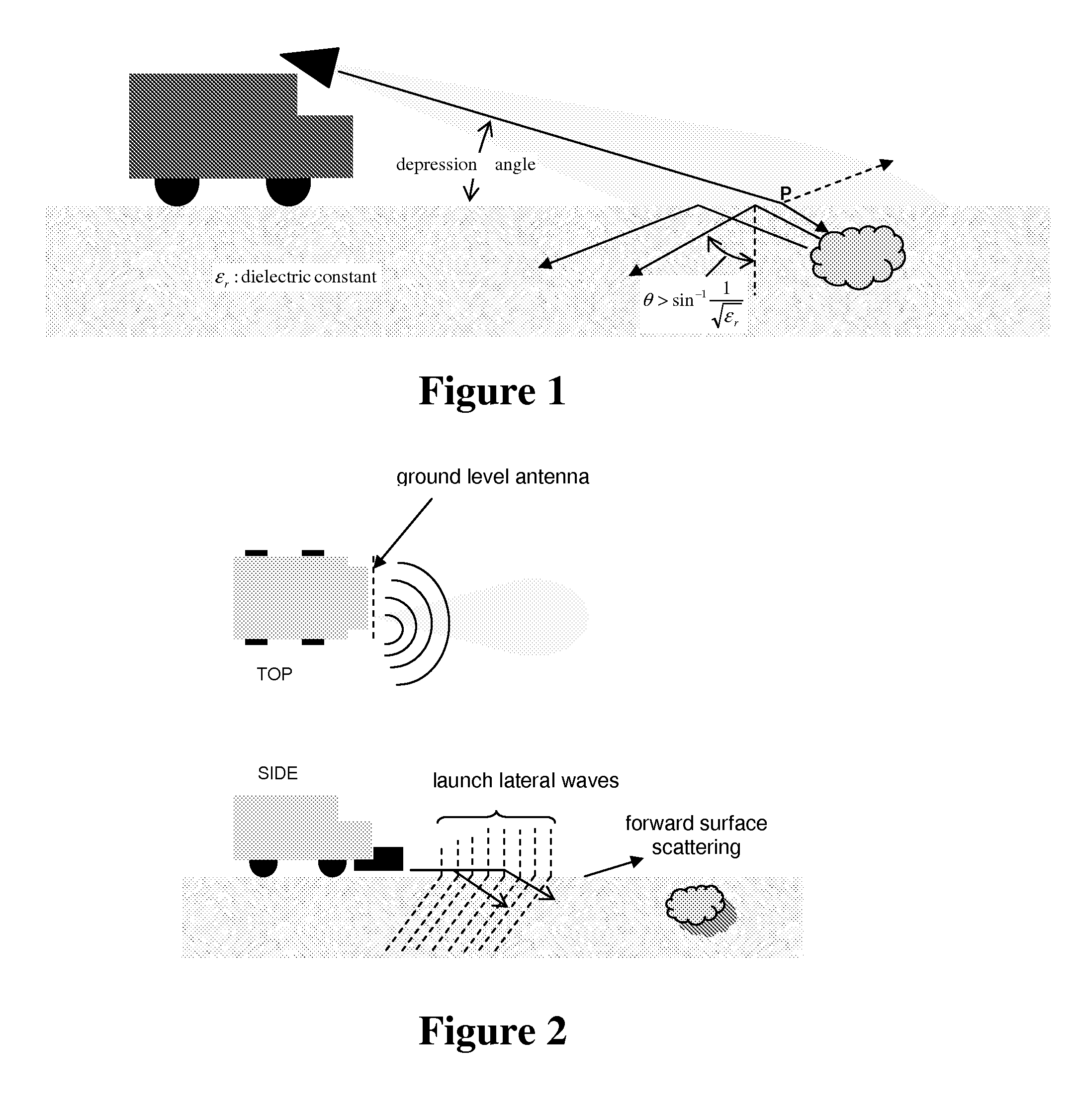
CROSS-REFERENCE TO RELATED APPLICATIONS[0001]This non-provisional patent application claims the benefit of priority to U.S. Provisional Patent Application No. 61 / 104,197, filed on Oct. 9, 2008, which is hereby incorporated by reference in its entirety.TECHNICAL FIELD[0002]The disclosed embodiments are in the field of radar detection, and more particularly in the field of radar detection of buried or near surface objects from a moving vehicle.BACKGROUND AND SUMMARY[0003]Although downward-looking ground penetrating radars have been developed for detecting buried objects, they are not able to reliably detect buried objects close to the front of a moving vehicle or to detect the at a significant distance. Forward-looking radar prototypes have been developed for buried-object detection with horn antennas mounted on top of a vehicle as illustrated in FIG. 1. It was bulky and showed very limited success according published results. These antennas are typically tilted downwards at a certain...

Claims


Application Information

Patent Timeline
Patent Type & Authority Applications(United States)
IPC IPC(8): G01S13/88
CPCG01S7/025G01S13/003G01S13/885G01S13/34G01S13/0209
Inventor CHEN, CHI-CHIH
Owner THE OHIO STATE UNIV RES FOUND
Learn More