
Gunshot detection system and method

a detection system and gunshot technology, applied in the field of muzzle flashes, can solve the problems of increasing the visibility of the shooter to the enemy, obscuring the target view, and not always convenient for the shooter, and achieve the effect of effective detection

Inactive Publication Date: 2011-07-14
ELTA SYST LTD
View PDF18 Cites 30 Cited by
  • Summary
  • Abstract
  • Description
  • Claims
  • Application Information

AI Technical Summary

Benefits of technology

The present invention provides an improved method for detecting high-speed light emission, including from firearms guns shots and muzzle flashes. This new technique allows for more accurate identification of these events.

Problems solved by technology

This patent discusses different ways to detect and locate weapon fired, particularly snipers. The technical problem addressed is finding effective and affordable methods without being obstructed by muzzle flash or excessive heat generated during combustion. Various techniques like muzzle flash detection through optical signals, analysis of shock waves created by the bursting of ammunition, and tracking of retro-reflected laser pulses have been developed but come with their own limitations and costs. Additionally, combining multiple detection methods could offer better results but requires further research and development.

Method used


Image

  • Gunshot detection system and method
  • Gunshot detection system and method
  • Gunshot detection system and method

Examples


Embodiment Construction

[0271]The present invention provides a novel technique for use in detection of short events, for example of a gunshot event including a muzzle flash event.

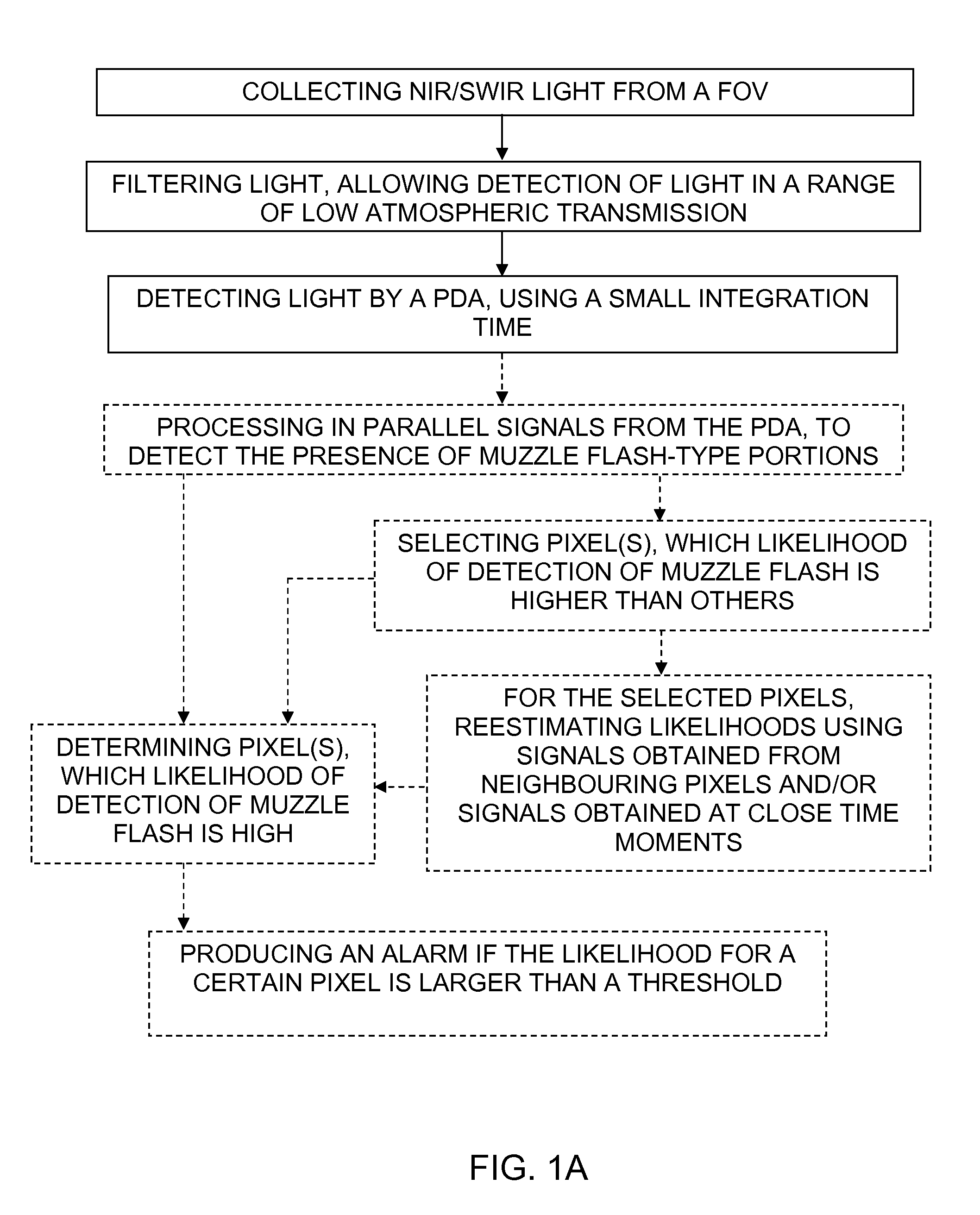
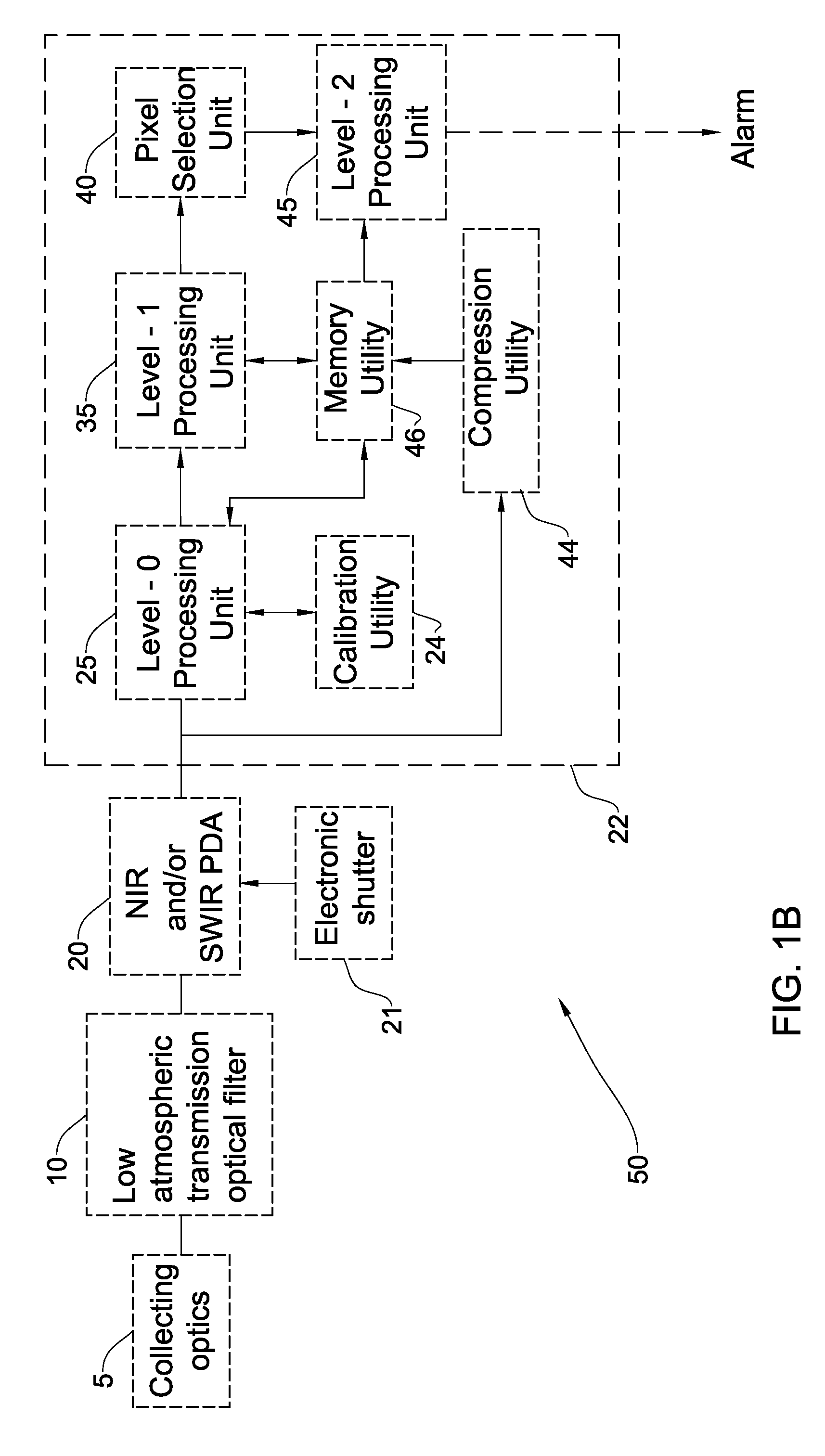
[0272]FIG. 1A shows a flow chart of the main steps in an example of the detection method of the invention. As shown, near infrared (NIR) and / or short wave infrared (SWIR) electromagnetic radiation, possibly including radiation emitted by an occurred muzzle flash, is collected from a field of view (FOV). The radiation is spectrally filtered for detection of substantially a spectral range corresponding to relatively low light transmission in atmosphere. As it has been found by the inventors, the muzzle flash radiation components being in such spectral range can provide a relatively high useful signal and signal-to-noise ratio, though they carry only a portion of overall muzzle flash intensity and are relatively short-existing. Also, it should be understood that only a portion of the collected light can be due to the muzzle flash eve...


PUM


Abstract

A device and a method for use in detection of a muzzle flash event is described. The device can include a Photo Detector Array (PDA), sensitive in at least a portion of the NIR and SWIR spectrum, and a filter of electromagnetic radiation selectively passing in this portion a spectral range of low atmospheric transmission, the PDA has an integration time shorter than a duration of the muzzle flash event.

Description


Claims


Application Information

Patent Timeline
Owner ELTA SYST LTD
Learn More