Steam turbine

Inactive Publication Date: 2011-07-14
KK TOSHIBA
View PDF9 Cites 9 Cited by
  • Summary
  • Abstract
  • Description
  • Claims
  • Application Information

AI Technical Summary

Problems solved by technology

Such a steam turbine may include many components in which required characteristics are not satisfied by the characteristics of the ferritic heat-resistant steel.
However, the austenitic steel has a limitation in producing a large steel ingot, making it difficult for the austenitic steal to be applied to the components of the steam turbine.
Among them, how the strengths of turbine components are guaranteed is particularly an important issue.
However, an increase in the steam temperature to 700 degree-C. or more makes it difficult to retain a high strength of the turbine components.
However, it is difficult to smoothly distributing the cooling steam inside the rotor which is a rotation field and to secure a sufficient flow rate of the coo

Method used


Image

  • Steam turbine
  • Steam turbine
  • Steam turbine

Examples


first embodiment

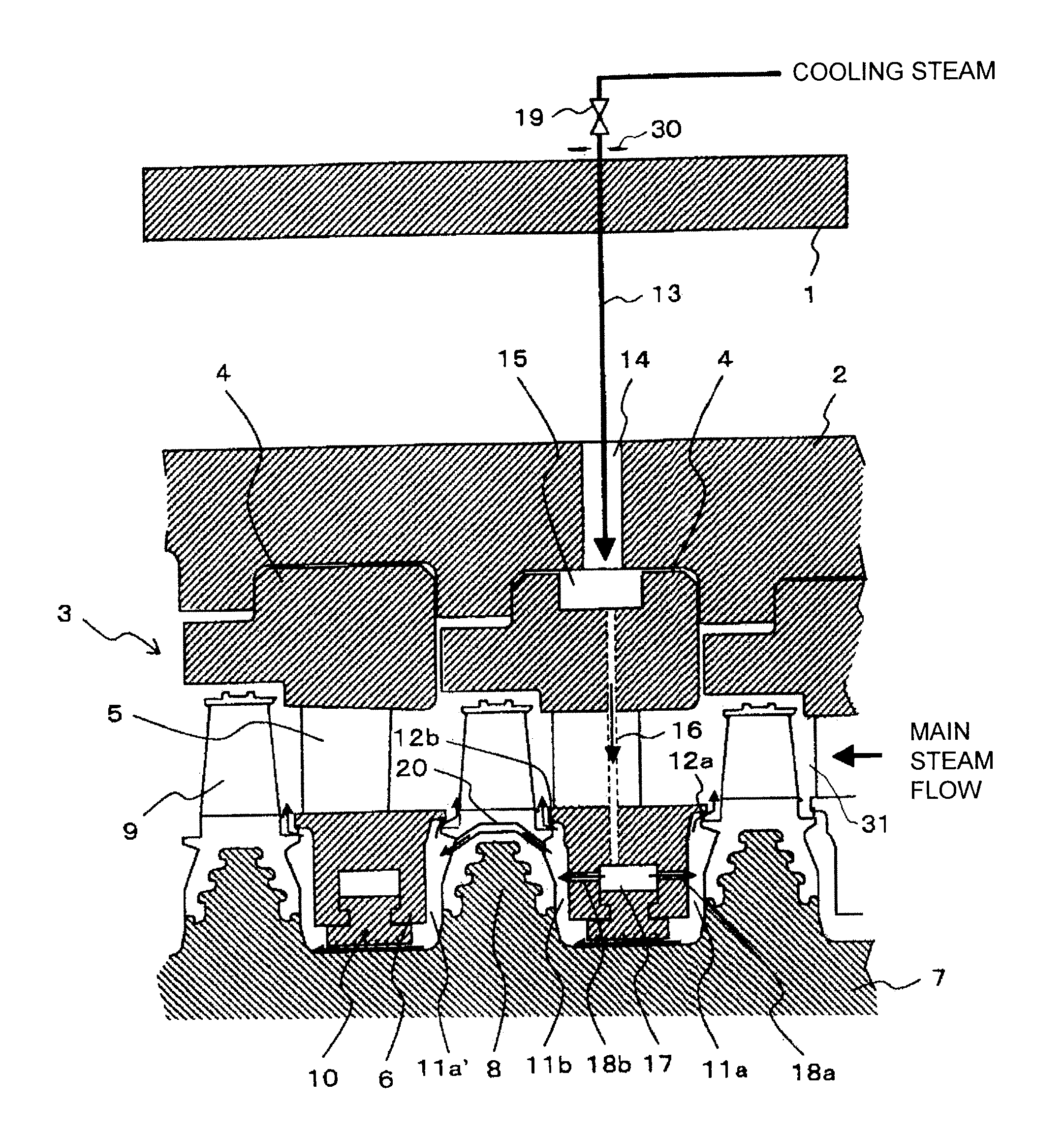
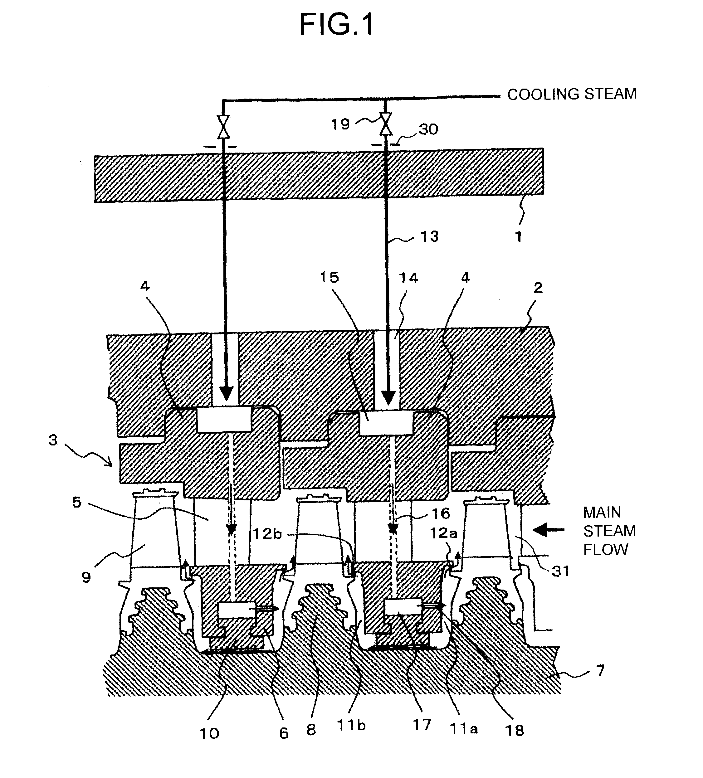
[0019]FIG. 1 is an axial direction cross-sectional view illustrating a steam turbine according to a first embodiment of the present invention.

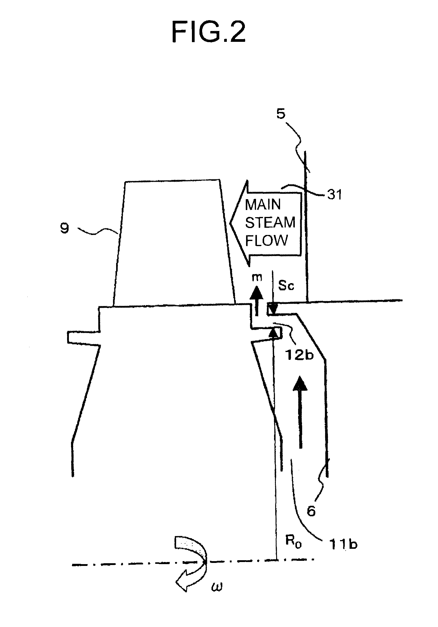
[0020]It is assumed that the right side on the paper surface of FIG. 1 is the upstream side and the left side thereof is the downstream side. The stationary side of the steam turbine includes an outer casing 1, an inner casing 2, and diaphragms 3 of individual stages. The diaphragm 3 includes an outer-ring 4, a plurality of stator blades 5, and an inner ring 6. The rotation side of the steam turbine includes a wheel type rotor 7 in which a rotor wheel 8 is formed for each stage and a plurality of rotor blades 9 implanted to the rotor wheel 8. Wheel spaces 11a and 11b are formed in a space between the inner ring 6 and rotor wheels 8 on the upstream and downstream sides of the inner ring 6. Main steam flowing through a main steam path 31 is prevented from flowing into the wheel spaces 11a and 11b by wheel space seal portions 12a and 12b such as ...

second embodiment

[0040]FIG. 3 is an axial direction cross-sectional view illustrating a steam turbine according to a second embodiment of the present invention.

[0041]In the first embodiment, the cooling steam is supplied to the outer ring cavity 15 on a per stage basis to cool individual turbine stage; while in the second embodiment, a configuration is adopted in which the cooling steam supplied to one stage is used to cool also an adjacent downstream stage. That is, the second embodiment aims at simplification of the structure.

[0042]In the steam turbine according to the second embodiment, a stage receives supply of the cooling steam from the outer ring side as in the first embodiment. To a stator blade upstream side wheel space 11a′ in the downstream side stage, the cooling steam is supplied from a balance hall 20 provided in a rotor blade fixing portion. The inner ring 6 has blowing holes 18a and 18b for blowing the cooling steam in both the directions toward the stator blade upstream side wheel s...

third embodiment

[0046]FIG. 4 is an axial direction cross-sectional view illustrating a steam turbine according to a third embodiment of the present invention.

[0047]In the present embodiment, in place of the balance hole 20 of the second embodiment, a plurality of intra-rotor connection holes 21 extending from the stator blade upstream side wheel space 11a to a stator blade upstream side wheel space 11a′ of the adjacent downstream stage are formed in the rotor over the entire circumference. The blowing holes 18b on the stator downstream side wheel space 11b side of the second embodiment can be omitted.

[0048]Operation of the present embodiment will next be described.

[0049]Part of cooling steam from the stator upstream side wheel space 11a directly flows into the stator blade upstream side wheel space 11a′ of the adjacent downstream stage to cool the rotor 7 of the downstream stage in the same manner as in the second embodiment.

[0050]According to the present embodiment, the same effect as in the secon...


PUM


Abstract

According to an embodiment, at least one first outer ring has an annular outer ring cavity to which external cooling steam is supplied. A radial direction cooling hole connecting with the outer ring cavity is formed in the stator blades connected to the first outer ring. An annular inner ring cavity connecting with the radial direction cooling hole is formed in a first inner ring constituting one diaphragm together with the first outer ring. Cooling steam blowing holes connecting an annular wheel space and the inner ring cavity are formed. The annular wheel space is formed between the first inner ring and a rotor wheel adjacent to the first inner ring.

Description

CROSS REFERENCES TO RELATED APPLICATIONS[0001]This application is based upon and claims the benefits of priority from the prior Japanese Patent Application No. 2010-004057, filed in the Japanese Patent Office on Jan. 12, 2010, the entire content of which is incorporated herein by reference.FIELD[0002]The embodiments of the present invention relates to a steam turbine provided with a rotor cooling method by supplying cooling steam from outside.BACKGROUND[0003]Ferritic heat-resistant steel excellent in productivity and economic efficiency has been used in the major part of the high temperature part of a thermal power generation plant. For example, in a steam turbine power generation plant in which steam temperature of 600 degree-C. class or less is generally set as the steam condition, the ferritic heat-resistant steel is used in main components such as a rotor or blades of the steam turbine. However, in recent years, the efficiency of the thermal power generation plant has been activ...

Claims


Application Information

Patent Timeline
IPC IPC(8): F01D5/18
CPCF01D5/081F01D9/065F05D2220/31F01D11/04F01D11/001
Inventor ITO, SHOKOSATO, IWATAROIKEDA, KAZUTAKAINOMATA, ASAKO
Owner KK TOSHIBA
Why Eureka
Try Eureka