

Method of manufacturing heat sink plate
- Summary
- Abstract
- Description
- Claims
- Application Information
AI Technical Summary
Benefits of technology
Problems solved by technology
Method used
Image

Examples
Embodiment Construction
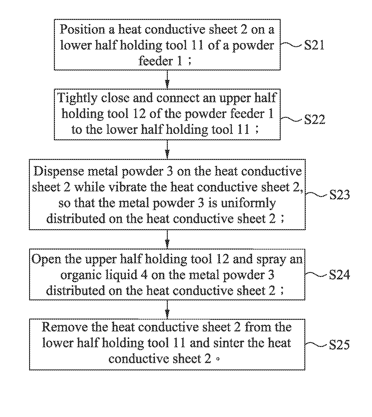
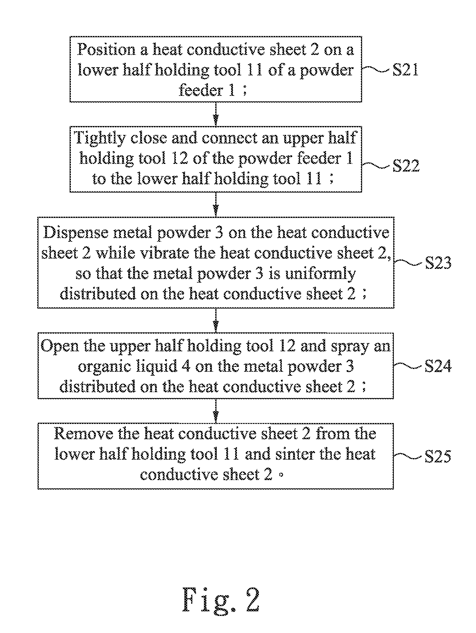
[0022]Please refer to FIG. 2 that is a flowchart showing the steps included in a method of manufacturing heat sink plate according to a first preferred embodiment of the present invention, and to FIGS. 4, 5, 6 and 8 that illustrate the manufacturing of a heat sink plate using the method shown in FIG. 2.
[0023]As shown in FIG. 2, the method of manufacturing heat sink plate according to the first preferred embodiment of the present invention includes the steps of:
positioning a heat conductive sheet 2 on a lower half holding tool 11 of a powder feeder 1 (step S21);
tightly closing and connecting an upper half holding tool 12 of the power feeder 1 to the lower half holding tool 11 (step S22);
dispensing metal powder 3 on the heat conductive sheet 2 while vibrating the heat conducting sheet 2, so that the metal powder 3 is uniformly distributed on the heat conductive sheet 2 (step S23);
opening the upper half holding tool 12 and spraying an organic liquid 4 on the metal powder 3 that has bee...
PUM
| Property | Measurement | Unit |
|---|---|---|
| Pressure | aaaaa | aaaaa |
| Electrical conductor | aaaaa | aaaaa |
| Heat | aaaaa | aaaaa |
Abstract
Description
Claims
Application Information