Tools for Seating Connectors on Substrates

a technology for seating connectors and substrates, which is applied in the direction of manufacturing tools, metal working apparatuses, printed circuit aspects, etc., can solve the problems of destroying connectors, affecting the service life of connectors, so as to reduce the damage to the connector and/or the substrate, reduce the damage to the connector and the substrate, and reduce the damage to the tool and the connector

Active Publication Date: 2015-05-07
BRIGHT MASCH INC
View PDF5 Cites 1 Cited by
  • Summary
  • Abstract
  • Description
  • Claims
  • Application Information

AI Technical Summary

Benefits of technology

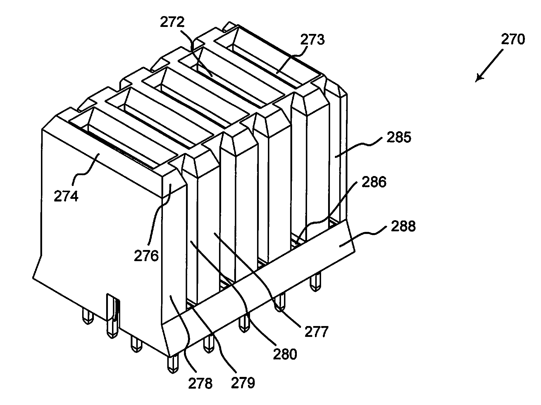
[0011]The present invention relates to connector tools for seating connectors on a substrate. In various embodiments, the connector tools can be made by the wire electrode discharge machining (WEDM) process. The connector tools include features such as reinforced ribbed end walls, ribbed internal walls, interconnected walls and contours that reduce tool and connector damage. The connector tools may include guiding structures that align the connector tool to the connector before seating the connector so that the connector tool aligns to the connector pins and body to avoid damage to the connector and / or the substrate. The connector tools may have guiding skirts and surfaces to capture the connector in position then seat the connector. Thus, the invention reduces connector and substrate damage during manufacturing, reduces tool damage, and lowers product costs by boosting manufacturing yields.

Problems solved by technology

If the connector does not seat, extracting and reseating connector may destroy the connector, damage the vias (i.e., the holes in the PCB) and any thin conductive traces in nearby vias.
Thus, more than one connector can be damaged in a single seating operation.
Despite use of high strength material, the delicate structures are susceptible to damage if dropped during a tool change or transportation.

Method used


Image

  • Tools for Seating Connectors on Substrates
  • Tools for Seating Connectors on Substrates
  • Tools for Seating Connectors on Substrates

Examples


Embodiment Construction

[0055]The following description includes the best mode of carrying out the invention. The detailed description is made for the purpose of illustrating the general principles of the invention and should not be taken in a limiting sense. The scope of the invention is determined by reference to the claims.

[0056]We assign each part, even if structurally identical to another part, its own reference number to help distinguish where the part appears in the drawings. We use dashed circles to indicate the parts that are enlarged in separate Figures. The separate Figure is indicated by the reference number tied to the dashed circle.

[0057]FIG. 6A is a perspective view of a connector tool 30 that includes a machined structure that has intersecting slots such as slots 36, 38 from wall-to-wall to mate with connector pins. In an embodiment, the machined structure is machined by WEDM. The connector tool 30 is used for the Tyco / AMP Z-PACK HS3 Backplane Connectors but the type of construction can be ...


PUM

PropertyMeasurementUnit
diameteraaaaaaaaaa
conductivityaaaaaaaaaa
strengthaaaaaaaaaa

Abstract

The present invention relates to connector tools for seating connectors on a substrate such as a printed circuit board. In various embodiments, the connector tools can be made by wire electrode discharge machining (WEDM) process. In the embodiments, the connector tool includes reinforced ribbed end walls, ribbed internal walls, interconnected walls and contours that reduce tool and connector damage. In other embodiments, the connector tools include guiding structures that align the connector tool to the connector before seating the connector so that the connector tool aligns to the connector pins and body to avoid damage to the connector and/or the substrate. In another embodiment, the connector tool has guiding skirts and surfaces to capture the connector in position then seat the connector. Thus, the invention reduces connector and substrate damage during manufacturing, reduces tool damage, and lowers product costs by boosting manufacturing yields.

Description

BACKGROUND[0001]This is a divisional of U.S. application Ser. No. 13 / 416,860, filed on Mar. 9, 2012, issuing as U.S. Pat. No. 8,578,596 on Nov. 12, 2013, which is a divisional of U.S. application Ser. No. 10 / 683,204, filed on Oct. 9, 2003, issuing as U.S. Pat. No. 8,136,233 on Mar. 20, 2012, which are both incorporated by reference herein.[0002]The present invention relates to connector tools for seating connectors on a substrate such as a printed circuit board (PCB).[0003]Connectors are used for data transfer interfaces in computers, buses, servers, and storage and networking systems. Some examples of connectors include the Tyco / AMP Z-PACK HS3 Backplane Connectors, the 2 mm hard metric connectors and the 2 mm VHDM connectors from Tyco / AMP, Molex, Erni, and FCI.[0004]The long, small diameter pins of these connectors may have gold plating to improve conductivity and performance at high frequencies and for corrosion protection. Care is required to prevent damage to the pins and the pl...

Claims


Application Information

Patent Timeline
Patent Type & Authority Applications(United States)
IPC IPC(8): H05K3/30
CPCH05K3/301H05K3/306H01R43/205H05K2201/10189H05K2203/0195Y10T29/53183
Inventor BARNHOUSE, ROBERT LEEHANCOCK, STEPHEN H.KAINEC, MARTIN H.
Owner BRIGHT MASCH INC
Why Eureka
Try Eureka