Dynamically adjustable dental impression devices and methods for using the same

a dynamic adjustment and dental impression technology, applied in the field of dental impression systems and methods, can solve the problems of large amount of impression material, inability to accurately create custom trays, and high cost of extra steps required to create custom trays, so as to increase the hydrostatic pressure within the quantity of impression material, and reduce the size of the internal cavity

Inactive Publication Date: 2011-07-14
ROSS DONALD H
View PDF3 Cites 14 Cited by
  • Summary
  • Abstract
  • Description
  • Claims
  • Application Information

AI Technical Summary

Benefits of technology

[0013]In some embodiments, the facial portion can be contracted with the lingual portion during the formation on the impression of the dental structure, resulting in the reduction in the size of the internal cavity. Additionally, in some embodiments, the reduction in the size of the internal cavity during the formation on the impression of the dental structure can increase the hydrostatic pressure within the quantity of impression material. Furthermore, the dynamically adjustable dental impression device can simultaneously apply forces substantially nonparallel and substantially parallel to the long axis of the tooth in the dental structure.
[0014]In addition to adjustable dental impression devices, the present invention provides methods for forming a dental impression. An exemplary embodiment of the method for forming a dental impression involves providing a dynamically adjustable dental impression device comprising a facial portion having at least a first wall and a lingual portion having at least a first wall. The facial portion is moveably connected to the lingual portion to form an internal cavity enabled to receive a quantity of impression material. The method for forming a dental impression further involves inserting the quantity of impression material into the internal cavity. Additionally, the method involves forming an impression by pressing a portion of the quantity of impression material in the dental impression device against a dental structure in a patient's mouth, and reducing the size of the internal cavity during the formation of the impression.

Problems solved by technology

These conventional stock size impression trays cannot be individually adapted to the teeth, so they typically require a relatively large amount of impression material and may not be as accurate as customized trays.
Although these systems allow for customized impression trays, the extra steps required to create the custom tray are relatively expensive and time consuming.
These bite tray impressions can result in distorted and inaccurate impressions if the lab does not pour the impression correctly (which is more difficult than with standard tray), the patient does not bite correctly or the oral tissues impinge on the tray.
This syringing technique is more time consuming and can lead to distortion by way of rebound if syringed into an already set preliminary impression when the tray is removed from the mouth.
Conventional impression trays often result in a void between the material and the dental structures being impressed.
These imperfections are often caused by air bubbles, contamination from tissue fluid, including blood, or by pulls on the thinner syringed material usually placed around the tooth or other dental structures of interest before the tray and its impression material is placed.
This is more likely to happen when the material is setting before final positioning of the tray, creating more drag.

Method used


Image

  • Dynamically adjustable dental impression devices and methods for using the same
  • Dynamically adjustable dental impression devices and methods for using the same
  • Dynamically adjustable dental impression devices and methods for using the same

Examples


Embodiment Construction

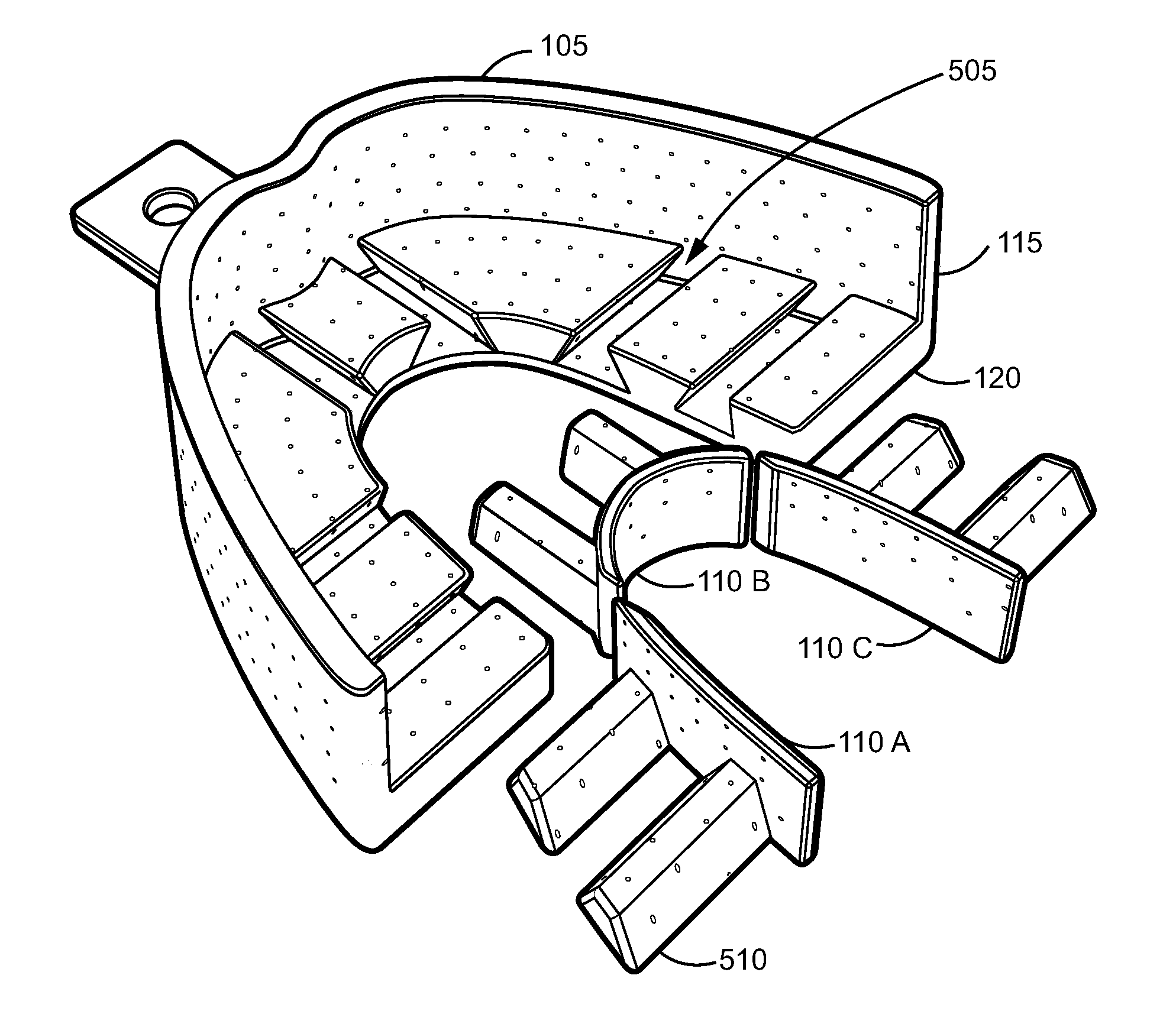
[0027]The present invention addresses the deficiencies in the prior art concerning the ability to provide quick, precise and accurate dental impressions. Significantly, the present invention provides methods and apparatus for providing dynamically adjustable dental impression devices. A dynamically adjustable dental impression device provided in accordance with the present invention is enabled to provide a precise and accurate model of a dental structure. The present invention overcomes the drawbacks of the conventional methods and systems in the prior art and provides systems and methods enabled to actively and dynamically adjust the dental impression device during the formation of an impression.

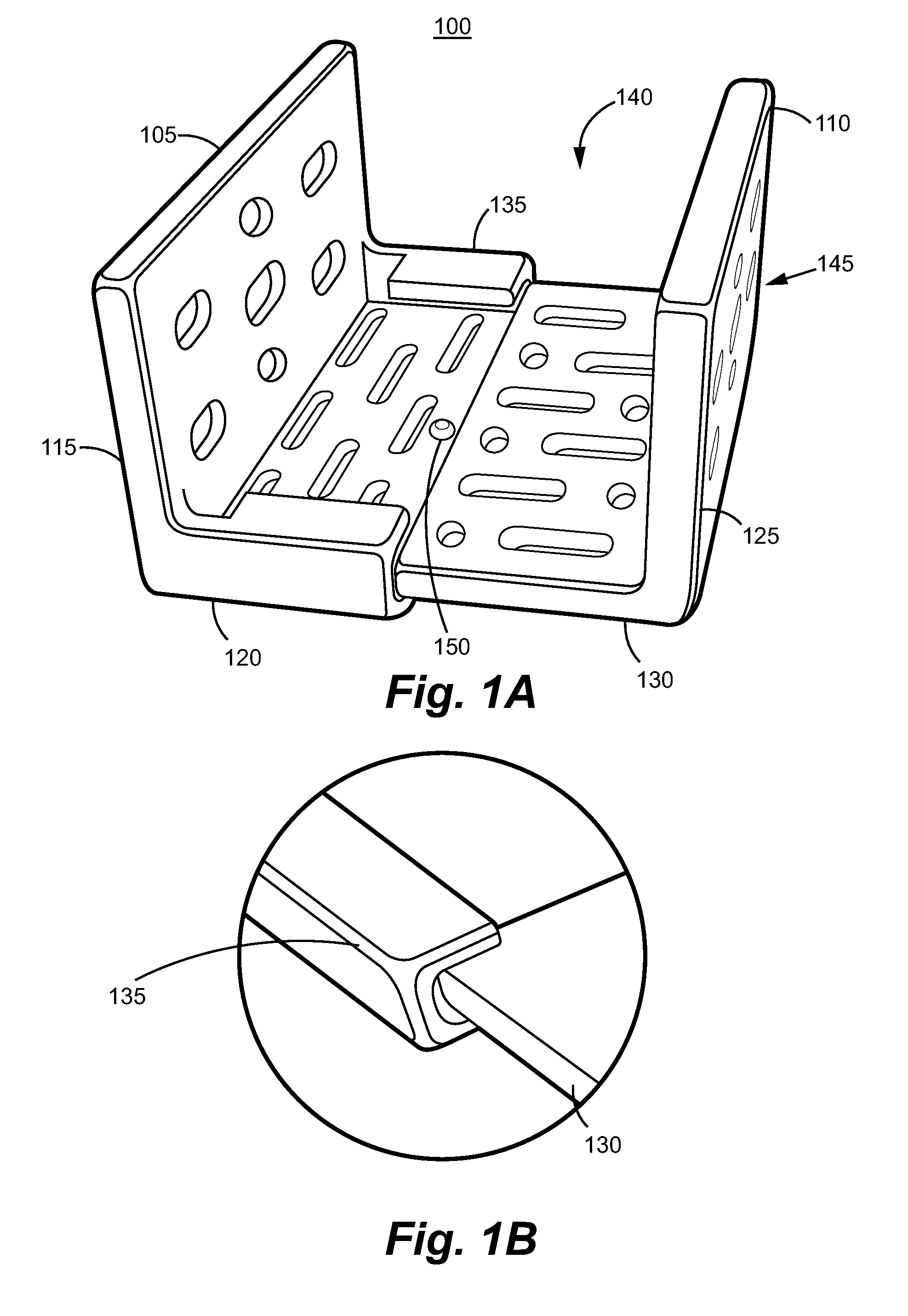
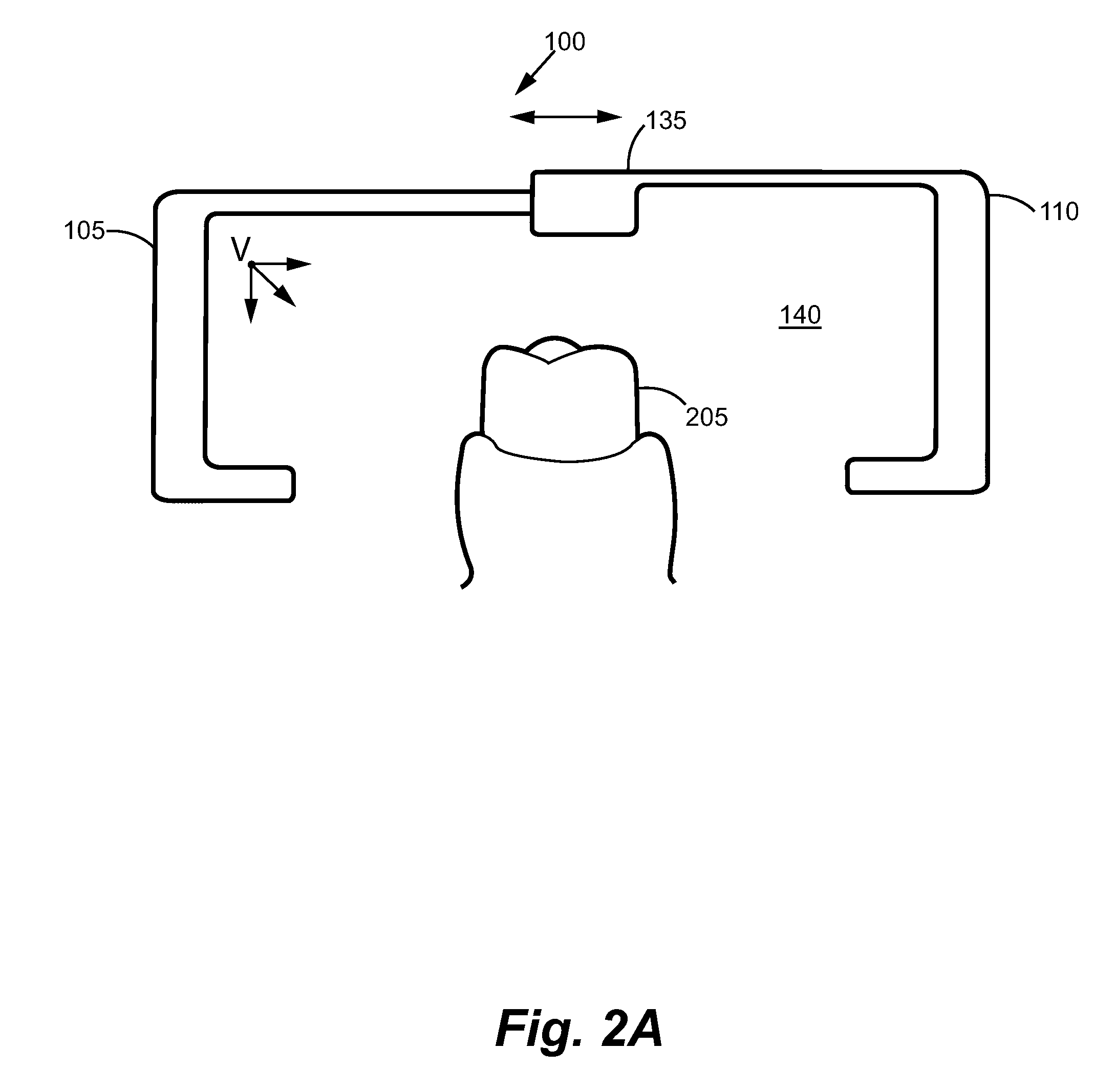
[0028]In an exemplary embodiment, the present invention provides a dynamically adjustable dental impression device including a facial portion having at least a first wall and a lingual portion having at least a first wall. The facial portion is movably connected to the lingual portion to fo...


PUM


Abstract

The present invention describes systems and methods to provide dynamically adjustable dental impression devices. In an exemplary embodiment, the present invention provides a dynamically adjustable dental impression device including a facial portion having at least a first wall and a lingual portion having at least a first wall. The facial portion is movably connected to the lingual portion to form an internal cavity enabled to receive a quantity of impression material. Furthermore, the size of the internal cavity can be reduced during the formation of an impression of a dental structure. In some embodiments, the facial portion can be contracted with the lingual portion during the formation on the impression of the dental structure, resulting in the reduction in the size of the internal cavity. Additionally, in some embodiments, the reduction in the size of the internal cavity during the formation on the impression of the dental structure can increase the hydrostatic pressure within the quantity of impression material. Furthermore, the dynamically adjustable dental impression device can simultaneously apply forces substantially nonparallel and substantially parallel to the long axis of the tooth in the dental structure.

Description

FIELD OF THE INVENTION[0001]The present invention relates generally to systems and methods for providing dental impressions and, more particularly, to systems and methods for providing dynamically adjustable dental impression devices.BACKGROUND OF THE INVENTION[0002]In dental therapeutics, the ability to create an accurate model of various dental structures, such as portions of a patient's teeth, tooth formations, implant parts, the contour of the gum, and adjacent portions of the jaw, is often critical to a successful procedure. An impression is often used to create an imprint or negative likeness of the teeth and / or implant related parts and adjacent portions of the jaw preparatory to dental repair, orthodontics and restoration or replacement of missing dental structures. Impressions are typically made by placing a soft, semi-fluid material within the confines of an open trough or channel of a unitary straight or arcuate tray, which is then positioned within the mouth of a patient...

Claims


Application Information

Patent Timeline
Patent Type & Authority Applications(United States)
IPC IPC(8): A61C9/00
CPCA61C9/0006
Inventor ROSS, DONALD H.
Owner ROSS DONALD H
Why Eureka
Try Eureka