Tool delivery systems and methods of use

a tool and tool technology, applied in the field of surgical tools, can solve the problems of limited scale of medical devices without the loss of functionality, inability to scale medical devices, and difficulty in delivering surgical instruments, etc., to achieve the maximum use of the guide tube channel width, reduce and reduce the effect of the likelihood of flexible tools snagging the walls

Inactive Publication Date: 2011-07-14
BOSTON SCI SCIMED INC
View PDF18 Cites 14 Cited by
  • Summary
  • Abstract
  • Description
  • Claims
  • Application Information

AI Technical Summary

Benefits of technology

[0005]Disclosed herein are various devices for use in delivering a tool to a procedure site within a patient. In one exemplary embodiment the delivery device includes a case or housing with an inner cavity sized and shaped to receive at least a portion of a flexible tool. The housing can reduce the likelihood of the flexible tool snagging the walls of a guide tube (i.e., delivery tube) and allow maximum use of the guide tube channel width. In addition, the inner cavity of the device can constrain the flexible tool and hold the flexible tool in a low profile configuration. The device (e.g., case or container) can also protect both the tool being transported and the working channel the tool is being t...

Problems solved by technology

Constraints on the size of anatomic passageways, surgical incisions, and/or instrument channels create particular challenges.
For example, the delivery of surgical instruments may be difficult or impo...

Method used


Image

  • Tool delivery systems and methods of use
  • Tool delivery systems and methods of use
  • Tool delivery systems and methods of use

Examples


case 105

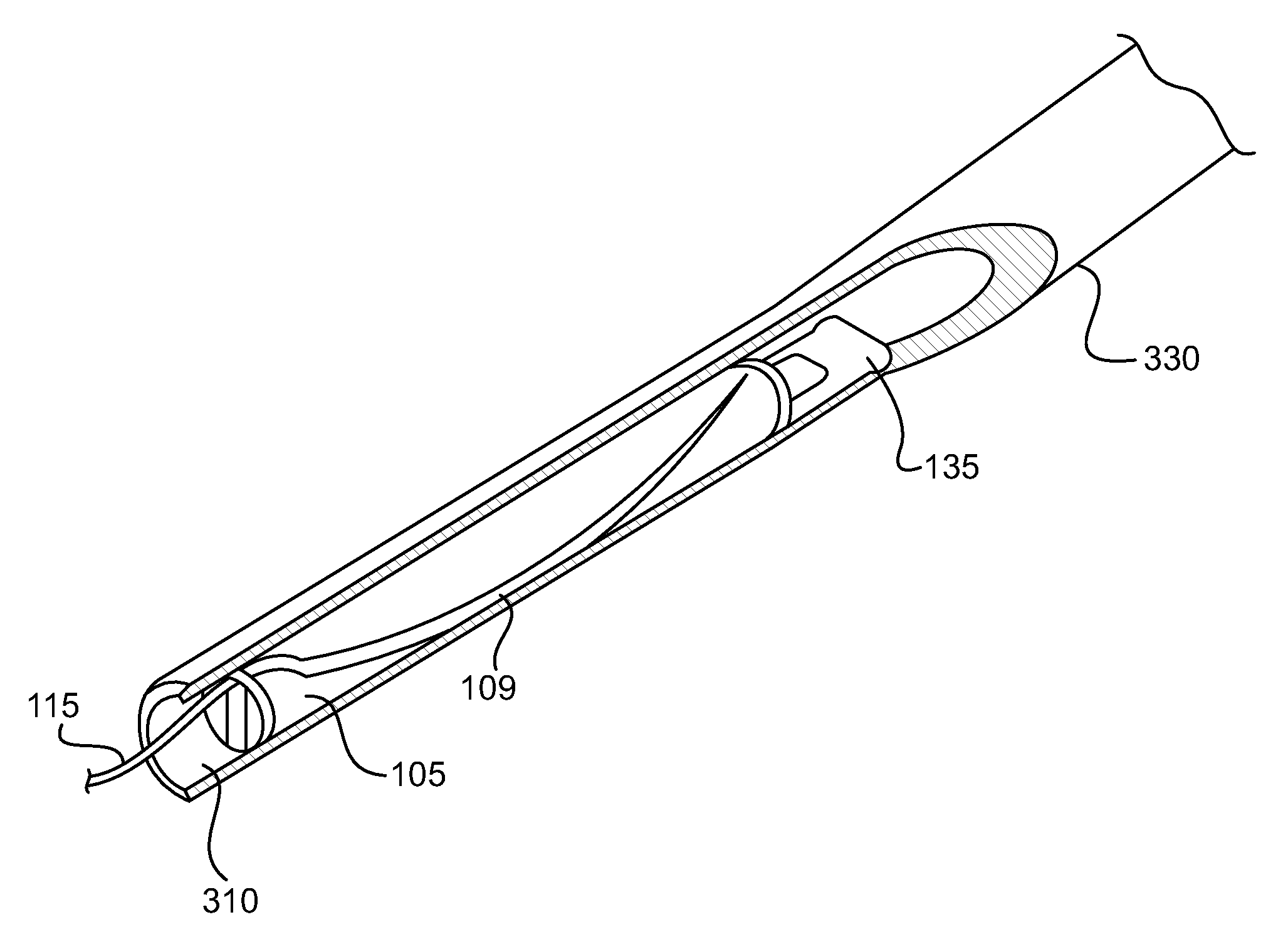
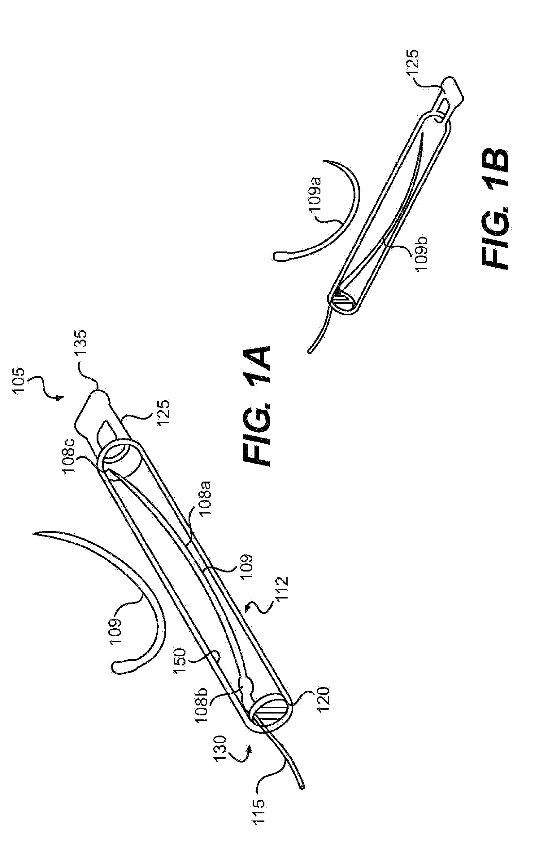
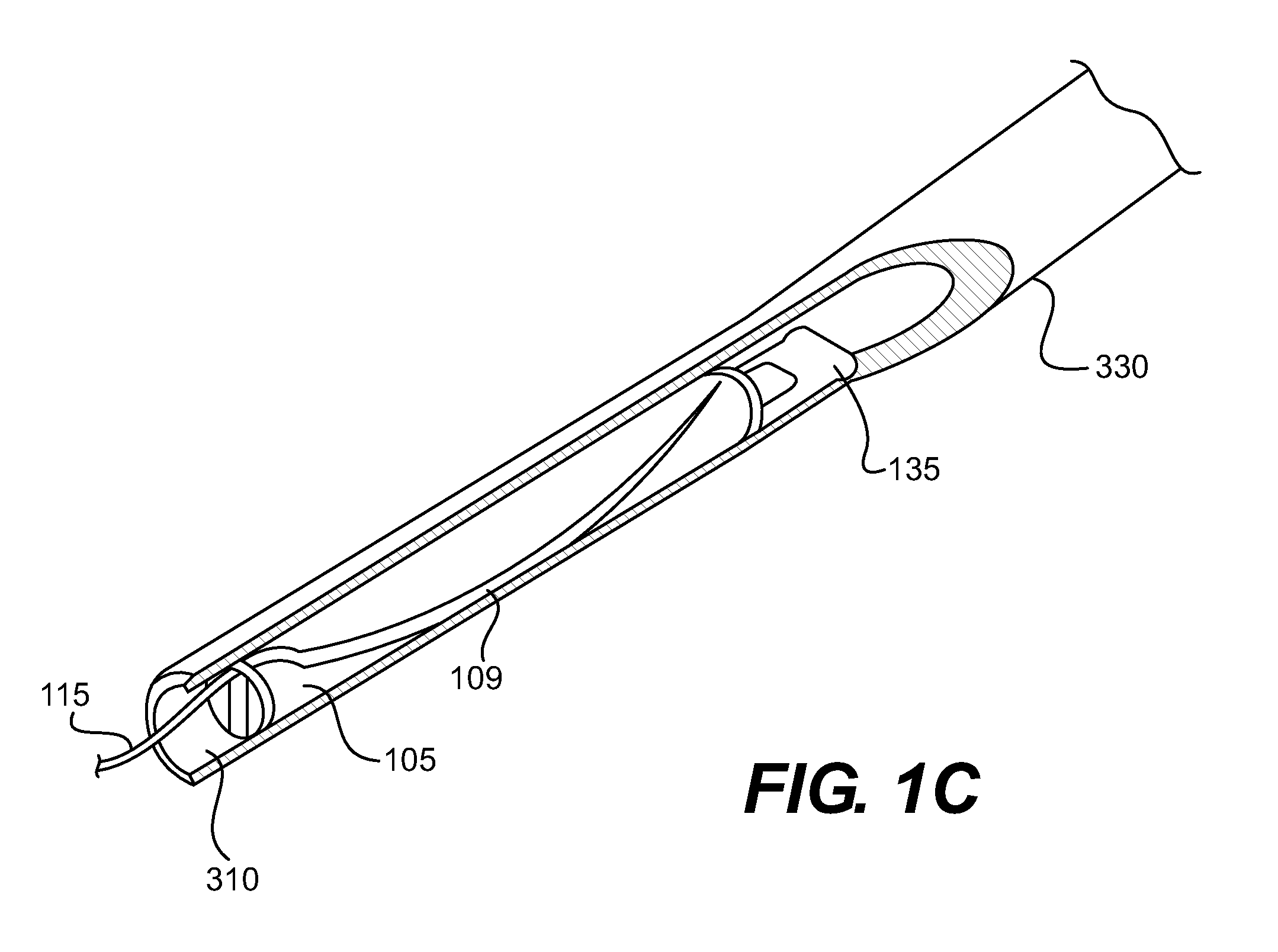
[0027]Case 105 can comprise an elongate body 112 with a first end 135 and a second end 130. In one aspect, first end 135 is a proximal end and second end 130 is a distal end. Body 112 can have an outer shape that corresponds in size and shape to the inner surface of a lumen extending through an elongate flexible instrument, such as a guide tube. The outer surface of case 105, in one aspect, can have a generally cylindrical shape. Alternatively, case 105 can correspond in size, but not shape, to the interior of a guide tube lumen. For example, the outer surface of the case can have a non-cylindrical shape, such as a polygonal cross-sectional shape or an irregular cross-sectional shape. It can accommodate a particular tool by having more space at one portion than at another portion of the container. Indeed, the body need not have a constant cross-sectional dimension. For example, body 112 can taper, be pill shaped, or otherwise have a variable diameter (i.e., width).

[0028]In one embod...


PUM


Abstract

Tool delivery systems and methods of use are disclosed herein. The delivery systems include a case for transporting a flexible tool to a procedure site and a guide tube. In one aspect, the flexible tool has a first size and shape greater than the diameter of a lumen within the guide tube. Placing the flexible tool into the case changes the flexible tool into a second, smaller size and shape and allows delivery of the needle through the guide tube.

Description

CROSS REFERENCE TO RELATED APPLICATIONS[0001]This application claims priority to U.S. Provisional Application No. 61 / 294,745, filed in the U.S. Patent and Trademark Office on Jan. 13, 2010, and incorporated herein by reference.BACKGROUND OF THE INVENTION[0002]Conventional surgical tools, such as endoscopic and laparoscopic devices, can provide surgical access to localized procedure sites while minimizing patient trauma. Although the growing capabilities of such therapeutic devices allow users to perform an increasing variety of surgeries through traditional minimally invasive routes, further refinements may allow surgical access through even less invasive routes and / or facilitate conventional surgical procedures.[0003]Constraints on the size of anatomic passageways, surgical incisions, and / or instrument channels create particular challenges. For example, the delivery of surgical instruments may be difficult or impossible. Accordingly, there is room for further refinement of tool del...

Claims


Application Information

Patent Timeline
IPC IPC(8): A61B17/062
CPCA61B17/0469A61B17/06128A61B2019/4805A61B2017/0479A61B2017/0608A61B2017/00862A61B2090/0801
Inventor KAPPEL, GARYWEITZNER, BARRYSMITH, PAUL
Owner BOSTON SCI SCIMED INC
Why Eureka
Try Eureka