Variable flow wastegate

a wastegate and variable flow technology, applied in the direction of machines/engines, manufacturing tools, mechanical apparatuses, etc., can solve the problems of less favorable matching, low efficiency, and low efficiency of the engine output and the turbocharger, and achieve the effect of cost-effectiveness

Active Publication Date: 2011-07-21
BORGWARNER INC
View PDF42 Cites 49 Cited by
  • Summary
  • Abstract
  • Description
  • Claims
  • Application Information

AI Technical Summary

Problems solved by technology

In a turbocharged engine system there is a basic mismatch between the engine output and the turbocharger output.
Determining that the sweet spot for the match is at rated point will produce less favorable matching at, for example, the low engine speed operating point.
This will mean that the engine will be more likely to produce more particulates in the engine low speed range than desired by the engine manufacturer (to meet emissions regulations) and the engine will not feel responsive to the driver.
However at Ne the turbocharger will over-boost the engine.
At the surge point, oscillatory flow behavior causes a flow blockage.
In the surge condition the flow detaches from the suction surface of the blade causing instability in the flow, which oscillates as the flow attaches and detaches from the blade.
In the choke regime, the turbo operates smoothly but the pressure ratio and efficiency fall, and temperatures rise.
There are many specifics outside of the turbocharger which cause there to be limits placed upon the turbocharger.
Limitations of the engine, such as cylinder pressure limits may mean that the boost level needs to be held below a maximum allowable pressure at any point in the engine operating regime.
Altitude limits may generate the need to control turbocharger speeds for structural reasons.
There are engine limiting factors, within the events of combustion, both internal and external to the combustion chamber.
The problem is that most wastegates are somewhat binary in their operation which does not fit well with the linear relationship between engine output and engine speed.
The problem with this “easy fix” is that since the simple flat faced valve and seat design does not modulate flow well with valve opening angle the operation of the wastegate can be coarse.
This reduces the energy available to drive the turbine wheel.
Since the escaping exhaust gas can only flow through the cylindrical orifice between the valve head and the valve seat, the flow change for a given valve displacement is not very linear.
But that adds significant cost to the engine since the electronics must live in a hostile environment of exhaust gas at approximately 860° C. to 1050° C. and vibration, both of which are hostile environments for electronics.

Method used


Image

  • Variable flow wastegate
  • Variable flow wastegate
  • Variable flow wastegate

Examples


Embodiment Construction

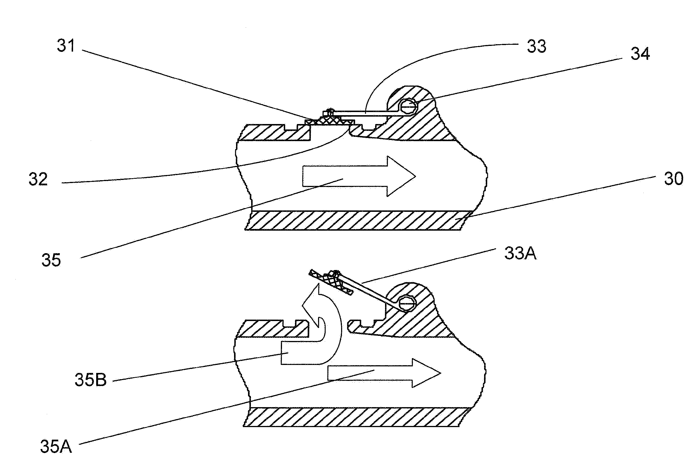
[0043]The invention discusses a novel change to both swing valve type and poppet type wastegates. Since the swing valve is the more common variety of wastegate, being more cost-effective to produce in volume, it is that variety which will be dealt with in this application. The person of ordinary skill will easily apply the principles illustrated with reference to the swing valve to the poppet type wastegate or any other type wastegate.

[0044]By incorporating a three dimensional horn on the face of the valve the opening of the valve, at both low and high degrees of opening, can be made to modulate exhaust gas flow in a more precise manner.

[0045]FIG. 6 depicts the configuration of a typical swing valve wastegate. The valve head (31) typically presents a flat face 36, of effective diameter (36A) to the sealing face (32) as it is the most cost-effective manufacturing solution. When the valve is open (see FIG. 533A) the exhaust gas flows out of the duct in a direction (35) towards the val...


PUM

PropertyMeasurementUnit
poweraaaaaaaaaa
poweraaaaaaaaaa
poweraaaaaaaaaa

Abstract

A wastegate for a turbocharger wherein the valve is provided with a horn to provide a more progressive, optimally near linear, curve of turbocharger boost-to-valve opening than possible with the typical flat wastegate valve. The addition of a three-dimensional horn in the flow path is a far more cost-effective solution to acquire linear flow than an approach involving very finite, accurate control of the valve position.

Description

FIELD OF THE INVENTION[0001]This invention is directed to the design of a wastegate flow path such that it produces a more progressive (consistent, most optimally near-linear) curve of flow through the orifice consisting of the stationary and dynamic valve components for a more progressive displacement of the valve.BACKGROUND OF THE INVENTION[0002]Turbochargers are a type of forced induction system. They deliver compressed air to the engine intake, allowing more fuel to be combusted, thus boosting the engine's horsepower without significantly increasing engine weight. This can enable the use of a smaller turbocharged engine, replacing a normally aspirated engine of a larger physical size, thus reducing the mass and aerodynamic frontal area of the vehicle.[0003]Turbochargers use the exhaust flow from the engine exhaust manifold to drive a turbine wheel located in a turbine housing. The turbine wheel is solidly affixed to one end of a shaft. A compressor wheel is mounted to the other ...

Claims


Application Information

Patent Timeline
Patent Type & Authority Applications(United States)
IPC IPC(8): F02D23/00
CPCF01D17/105F02B37/183F05D2220/40Y02T10/144F02B39/00Y02T10/12F02B37/12F02B37/18F16K1/38
Inventor GRABOWSKA, DAVID G.
Owner BORGWARNER INC
Why Eureka
Try Eureka