
Landing gear mechanism for aircraft

Active Publication Date: 2011-07-21
EMBRAER SA
View PDF22 Cites 4 Cited by
  • Summary
  • Abstract
  • Description
  • Claims
  • Application Information

AI Technical Summary

Benefits of technology

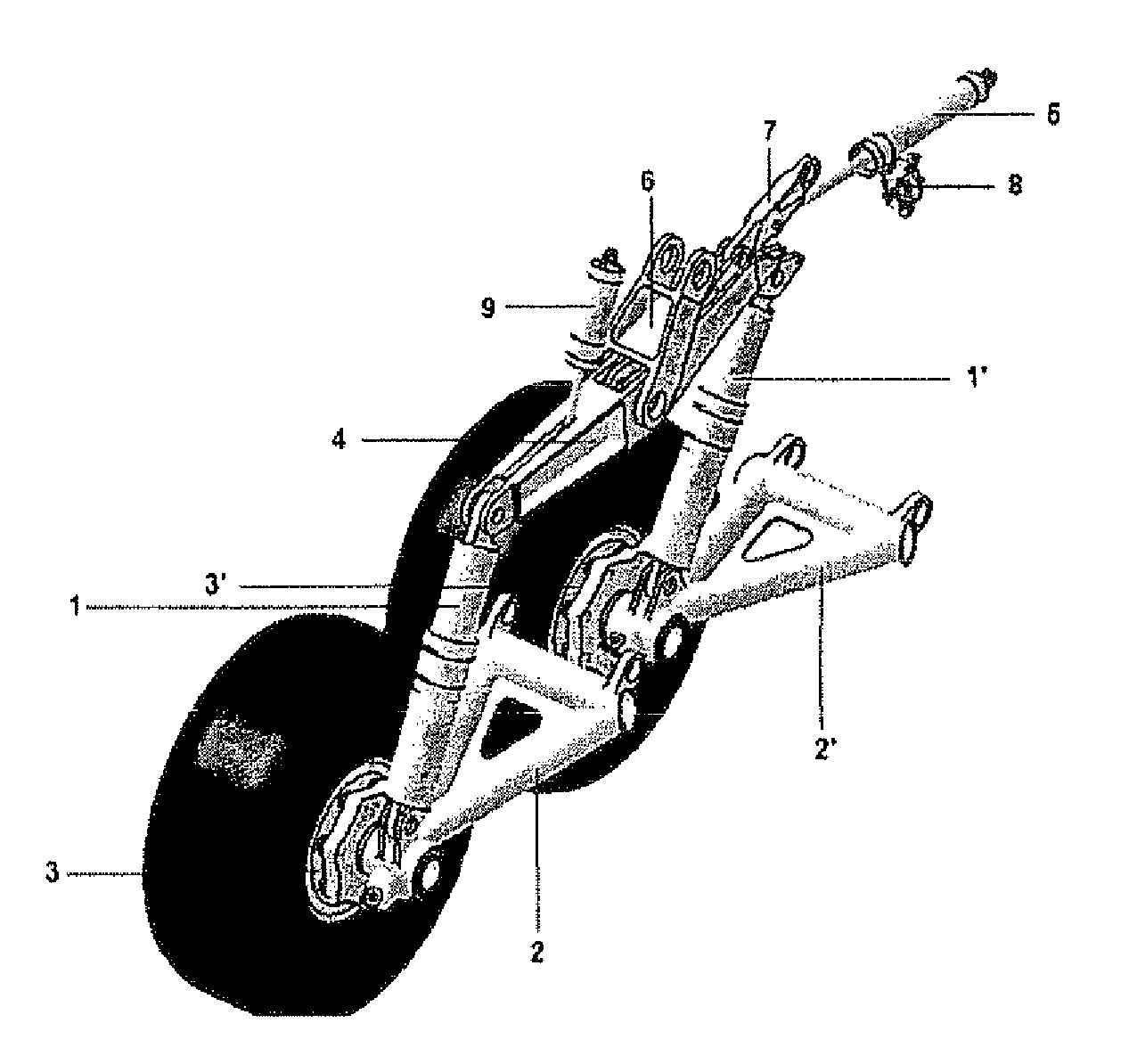
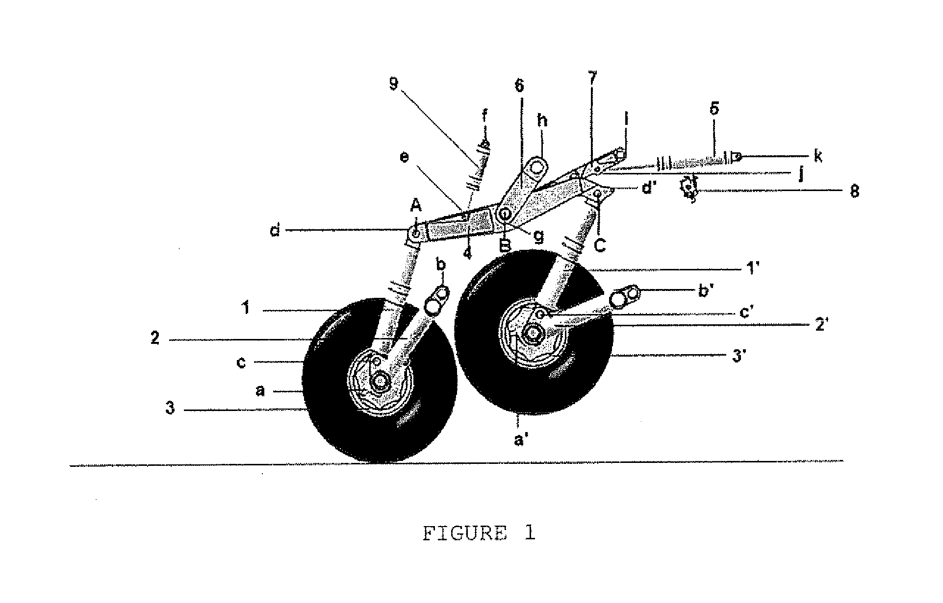
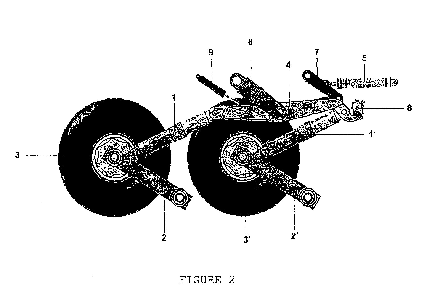
This set of wheels, shock absorber elements and connecting arms operatively cooperates with the balance beam, which makes said elements work in synchronism. That is, when a wheel goes down the other goes up and vice-versa. Due to the fact that shock absorbers are indirectly connected by the balance beam, the strokes of the front and rear shock absorbers are summed, thereby ensuring the high efficiency of the damping set. This creates an interdependence between the front and rear wheels. Such interdependence ensures a balanced load distribution between the two wheels, regardless of any irregularities in the ground.

Problems solved by technology

a) it has an independent set for each leg, which is fixed to the aircraft structure;
b) each leg comprises a positioning actuator;
c) the landing gear does not have a structure that provides a synchronized movement of the balancing efforts between the front and rear wheels for landing on runways whose grounds are irregular and not prepared;
d) overload in certain parts of the set; and
e) complex control circuits in dampers and positioning actuators.
Moreover, none of the prior art documents has a landing gear whose structure is provided with a mechanism that allows the wheels to fit the irregular ground of runways on unprepared grounds.

Method used


Image

  • Landing gear mechanism for aircraft
  • Landing gear mechanism for aircraft
  • Landing gear mechanism for aircraft

Examples


second embodiment

FIGS. 5 to 7 show a second embodiment, designed for the present invention. In this embodiment, the maneuvering actuator 5 comprises one hinged end (p), which is connected to an upper part of the balance beam (4). The other end of the maneuvering actuator (5) is hingedly connected to the upper part of the rear bellcrank (11). The rear bellcrank (11) is indirectly and hingedly connected to the frontal bellcrank (11′) by a connecting bar (12), which is disposed below and parallel to the balance beam (4). The rear and front bellcranks (11, 11′) indirectly and hingedly link the balance beam (4) to the rear and front shock absorbers (1, 1′), respectively.

In addition, in this configuration the central part of the balance beam (4) is hingedly connected to the aircraft structure (10). Thus, the balance beam (4) does not promote a back and forth movement with respect to the horizontal plane, but only semi-rotation movements. The positioning damper element (9) interconnects the front bellcrank...

fourth embodiment

In the fourth embodiment, as well as in the third one, according to FIG. 10, the positioning damper element (9) has its second end hingedly connected to the aircraft structure (10) and its first end is hingedly connected to the arm (B1), which in turn is connected to the balance beam (4). According to FIG. 16, when the landing gear is in the retracted position, the shield (16) is positioned in front of the channel of the pin (17) through an automatic shifting, which is promoted by a torsion spring coupled to the same. The positioning of the shield (16) before the channel of the pin (17) aims to prevent the pin (17) to be extended as in FIG. 15a, when the landing gear is retracted.

FIGS. 18 and 19 show a fifth embodiment designed for the present invention. Said embodiment also comprises a first front sub-set formed by a connecting arm (2′), at least one wheel (3′) and a shock absorber (1′), and a rear sub-set formed by a connecting arm (2), at least one wheel (3) and a shock absorber ...

third embodiment

Its main feature is the arrangement of its components for locking and driving the landing gear. This arrangement is different from the previous ones, mainly the third embodiment, due to the arrangement of the semi-arms that are comprised by the locking arm (7), which will provide a force distribution between the semi-arms in a different manner between this embodiment and the third one.

According to FIG. 20, in the extended position the landing gear shows in its central region a locking arm (7) formed by the semi-arms (7a), (7b), (7c), (7d) and (7e), which are hinged to each other. At the time when the landing gear is in the extended position, said arms are disposed so that the first end of (7a) is angularly connected to the first end of (7b); the second end of (7b) is angularly connected to the first end of (7c); the second end of (7c) is connected in a straight and locked manner to the first end of (7d); the second end of (7d) is angularly connected to the second end of (7a). Moreov...


PUM


Abstract

Landing gear mechanism for aircraft comprising at least a first connecting arm (2′) and a second connecting arm (2), at least a front wheel (3′) and rear wheels (3) each associated with one of the connecting arms (2′, 2) with a balance beam element (4), which is indirectly linked to said front and rear wheels (3′, 3) through each one of the connecting arms (2′, 2) and each one of the shock absorber elements (1′, 1), respectively, so that the front portion of the balance beam element (4) is associated with the first portion of the first shock absorber element (1′), which in turn has a second portion associated with a first portion of the first connecting arm (2′), which in turn has a second portion associated with the aircraft structure (10), and said rear portion of the balance beam element (4) is associated with a first portion of the second shock absorber element (1), which in turn has a second portion associated with a first portion of the second connecting arm (2), which in turn has a second portion associated with the aircraft structure (10), further comprising the positioning damper element (9) hingedly connected to the aircraft structure (10) and also connected, directly or indirectly, to a portion of the body of the balance beam element (4).

Description

FIELD OF INVENTIONThe present invention relates to a landing gear mechanism for use in aircraft, preferably for retractable landing gears, which allows to be retracted on the fuselage of the same, whose use is required in aircrafts for cargo transportation.BACKGROUND OF THE INVENTIONExisting landing gears used in freight aircraft have a robust structure to support, at the time of landing, the high impact loads on the ground, especially those landings on unprepared runways, whose ground is irregular. Such structures are based on independent sets of arms to support the wheels, said arms being attached to the fuselage of the aircraft and offering complex and not so effective embodiments, because of the independence of movement of the arms.In this sense, the difficulty that the aircraft faces on landing on runways with irregular ground, particularly freight aircraft, is true, because the structures of the existing landing gears, particularly the arms to support the wheels, are not synch...

Claims


Application Information

Patent Timeline
IPC IPC(8): B64C25/10B64C25/18B64C25/26
CPCB64C25/14B64C2025/125B64C25/34
Inventor FERRAZ, MARIO SERGIO DIAS
Owner EMBRAER SA
Learn More