Temperature Compensation Device and Method for MEMS Resonator

Inactive Publication Date: 2011-07-21
INTERUNIVERSITAIR MICRO ELECTRONICS CENT (IMEC VZW)
View PDF6 Cites 8 Cited by
  • Summary
  • Abstract
  • Description
  • Claims
  • Application Information

AI Technical Summary

Benefits of technology

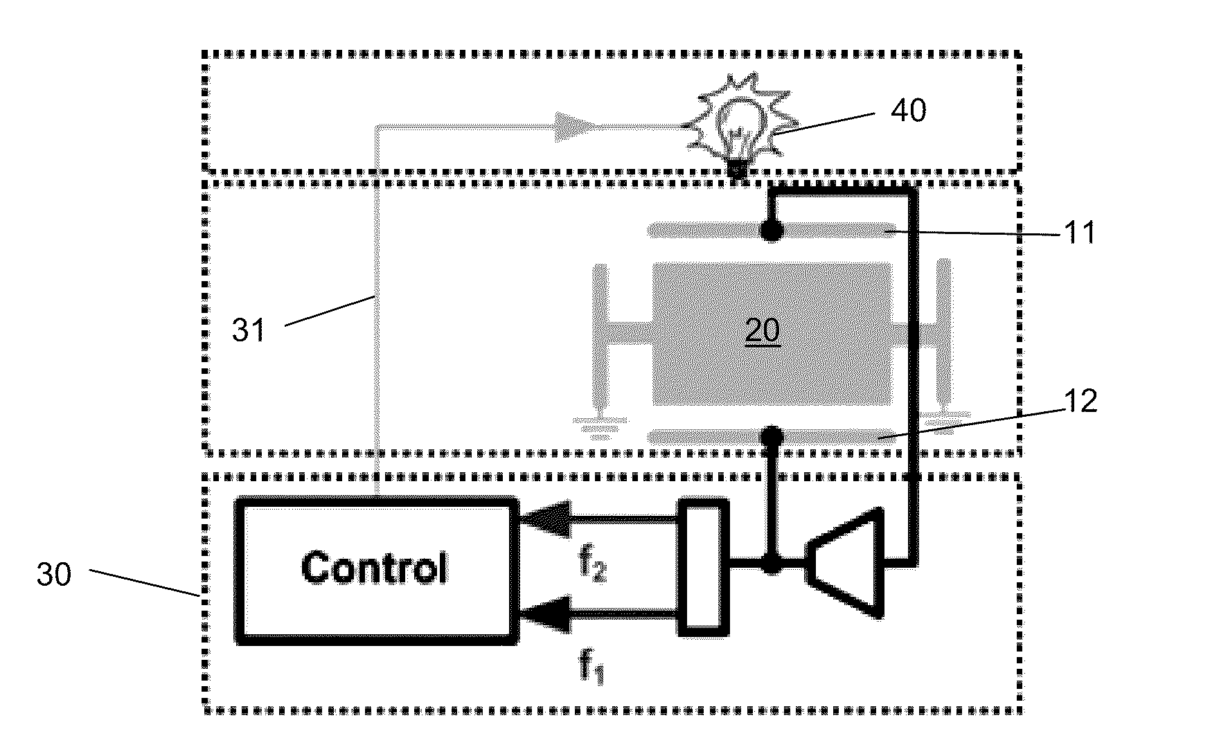
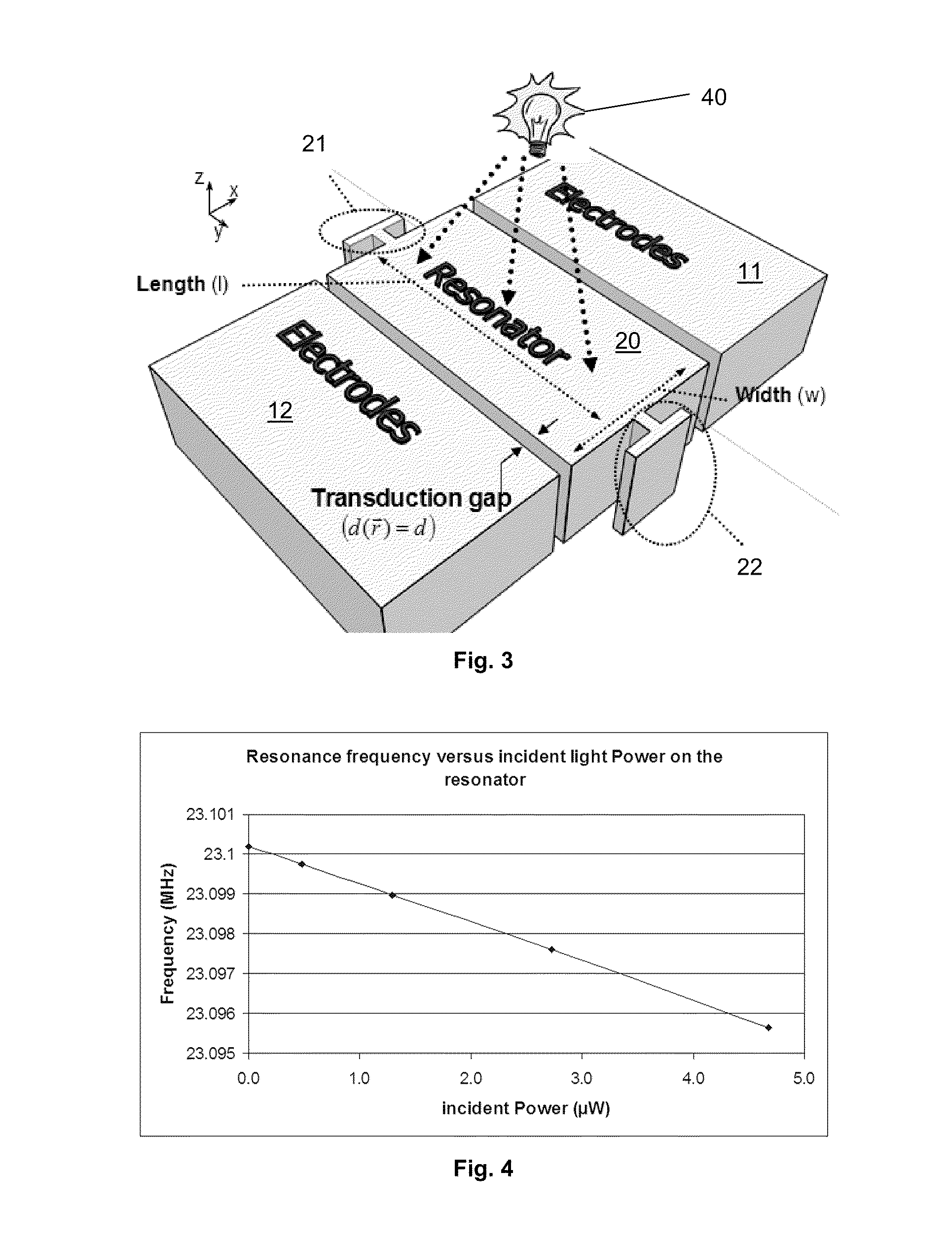
[0014]By providing thermal energy in the form of thermal radiation, the thermal energy can be focused towards the MEMS resonating element, thereby reducing or even avoiding directly heating the surroundings of the MEMS resonating element. As the thermal energy can be more directly absorbed by the MEMS resonating element, a much higher reaction speed to temperature variations can be achieved compared to prior devices.
[0015]In an embodiment, the MEMS resonating element may be fabricated in a material having a low thermal conductivity, such as, for example, silicon-germanium (SiGe), metals, permalloy, vanadium oxide, or (poly-crystalline) silicon. SiGe is a material having low thermal conductivity, allowing the effective confinement of the absorbed thermal radiation to the resonator itself and reducing a loss of thermal energy. This makes it possible to use higher operational temperatures. A typical operation interval ranges from −20° C. up to 90° C. The energy confinement may increase the range over which the temperature dependent parameter(s) of the MEMS resonating element can be tuned as a function of the operat

Problems solved by technology

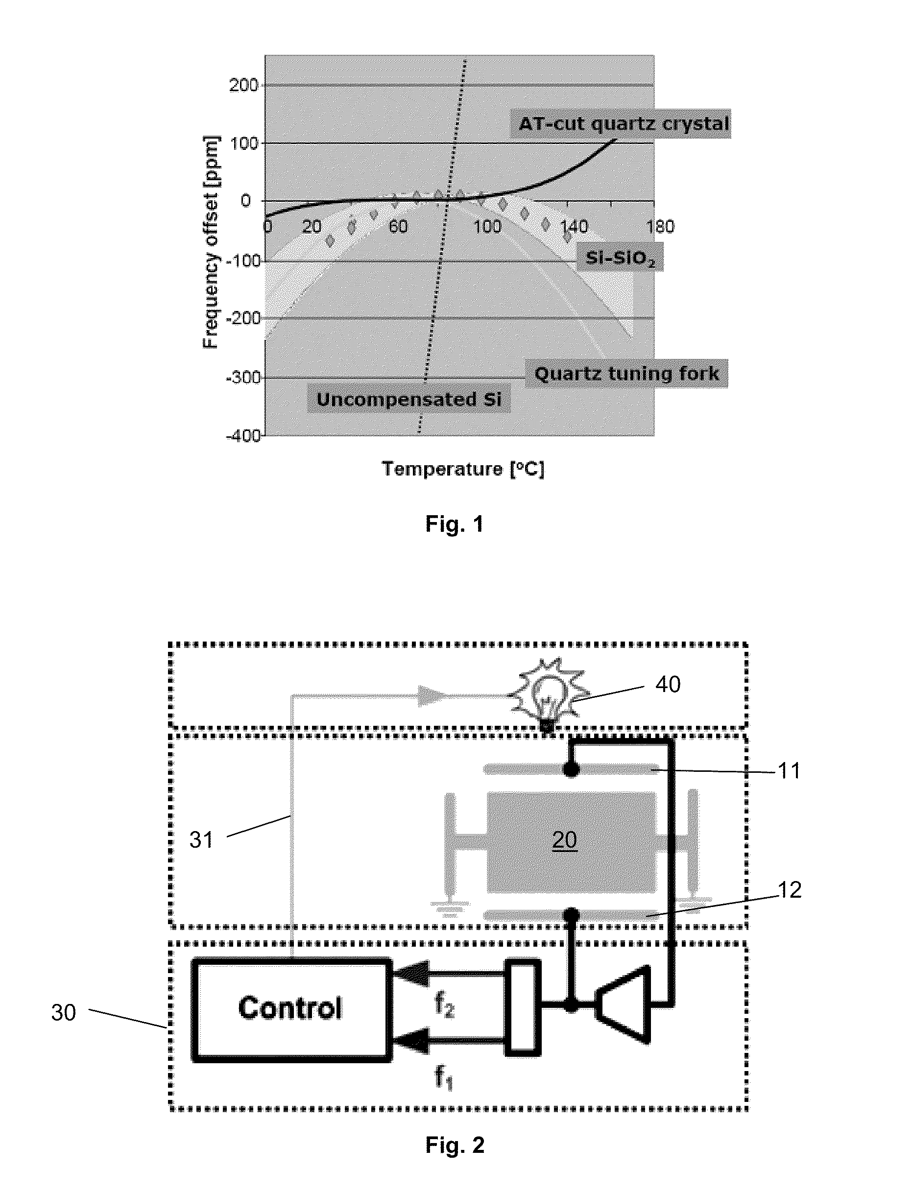
One of the drawbacks of these MEMS resonators is the reson

Method used


Image

  • Temperature Compensation Device and Method for MEMS Resonator
  • Temperature Compensation Device and Method for MEMS Resonator
  • Temperature Compensation Device and Method for MEMS Resonator

Examples


Embodiment Construction

[0029]The present disclosure will be described with respect to particular embodiments and with reference to certain drawings but the disclosure is not limited thereto but only by the claims. The attached Figures are only schematic drawings and are non-limiting. In the drawings, the size of some of the elements may be exaggerated and not drawn to scale, for illustrative purposes. The dimensions and the relative dimensions do not necessarily correspond to actual reductions to practice of the disclosure.

[0030]Furthermore, the terms first, second, third, and the like in the description and in the claims, are used for distinguishing between similar elements and not necessarily for describing a sequential or chronological order. The terms are interchangeable under appropriate circumstances and the embodiments of the disclosure can operate in other sequences than described or illustrated herein.

[0031]Moreover, the terms top, bottom, over, under, and the like in the description and the clai...


PUM


Abstract

The present disclosure provides a device including a MEMS resonating element, provided for resonating at a predetermined resonance frequency, the MEMS resonating element having at least one temperature dependent characteristic, a heating circuit arranged for heating the MEMS resonating element to an offset temperature (Toffset), a sensing circuit associated with the MEMS resonating element and provided for sensing its temperature dependent characteristic, and a control circuit connected to the sensing circuit for receiving measurement signals indicative of the sensed temperature dependent characteristic and connected to the heating circuit for supplying a control signal thereto to maintain the temperature of the MEMS resonating element at the offset temperature. The heating circuit includes a tunable thermal radiation source and the MEMS resonating element is provided so as to absorb at least a portion of the thermal radiation generated by the tunable thermal radiation source.

Description

CROSS-REFERENCE TO RELATED APPLICATIONS[0001]The present application claims priority to U.S. Provisional Patent Application Ser. No. 61 / 297,009, filed in the United States Patent and Trademark Office on Jan. 21, 2010, the entire contents of which is incorporated herein by reference.BACKGROUND[0002]1. Field of the Invention[0003]The present disclosure relates to a device and a method for compensating the temperature in a MEMS resonator.[0004]2. Description of the Related Art[0005]Micro-electromechanical systems (MEMS) resonators can be used as accurate timing references, to replace, for example, quartz crystals in timing circuits as disclosed by W. T. Hsu, J. R. Clark, et al., in “Mechanically temperature-compensated flexural-mode micromechanical resonators,” Technical Digest International Electron Devices Meeting 2000 (IEDM2000), pp. 399-402, hereby incorporated by reference in its entirety. One of the drawbacks of these MEMS resonators is the resonant frequency drift with respect t...

Claims


Application Information

Patent Timeline
IPC IPC(8): H03H9/08
CPCH03H9/02448
Inventor STOFFELS, STEVETILMANS, HENDRIKUS
Owner INTERUNIVERSITAIR MICRO ELECTRONICS CENT (IMEC VZW)
Why Eureka
Try Eureka